For a while now I’ve wanted to replace the crappy, noisy pots that I’d used in my Jentron MK2 gimbal that was in the 109F/X #0 cockpit.  They were so bad that it was impossible to use the gimbal for flight at all.

The best way to replace a mechanical potentiometer is to use a hall effect device.  This is essentially a sensor that will output a 0 to 5v signal based on the position of a magnet.  I’m using the Allegro 1302 for this project.  It works very, very well and can be a direct replacement for any three wire pot installation.

My design uses a 7/8″ (22mm actually) bearing with an 8mm center bore.  The center bore allows you to use a “traditional” Bic pen body as an input shaft.  You can press the body segment into the bearing and it won’t be coming out any time soon!  You can purchase the bearings here: http://www.vxb.com/page/bearings/PROD/SB/Kit1063

I installed the pen body into the bearing and then glued a pair of 1/4″ square neodymium magnets (oriented NS-pen-NS) to either side of the pen body with some thick Cyanoacrylate glue.  Works great!

In order to be a direct replacement for the pots, I needed to add similar control arms to them.  I did this by laser cutting a press-fit back plate that I threaded for #4-40 screws.
Continue Reading

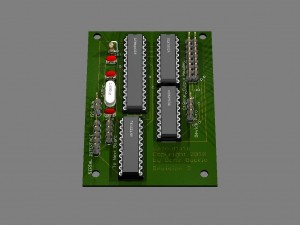
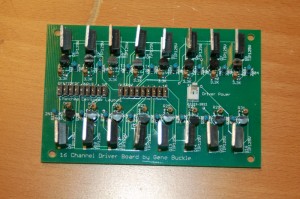
Just before heading off for what I suspect will be a “nom-fest”, I wanted to post a picture of my new 16 channel driver board:

It doesn’t look like much, but this is what I’ll use in the F-15 to drive all the indicator lamps.  The board is designed to be directly connected to the Centipede Shield by MaceTech.

There is an error on the board – though.  Can you spot it? 😀

Happy Thanksgiving!

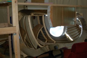
The world’s first amateur built cross-cockpit collimated video display system:

This is a 60 degree wide by 40 degree high spherical section collimating mirror.

More information can be found here: http://www.diy-cockpits.org/coll/collimated_display.html

Until yesterday (11/20/2010) this kind of thing was the sole domain of multi-million dollar commercial flight simulators.  Not. Any. More. 😀

Thanks all!

g.

..are now DonationWare!

You can download the 386MB ISO from here.

There’s no difference in the content between the commercial edition that I was selling and this one, with the exception of the cost.  It’s purely donation-ware at this point.  Pay what you feel it’s worth to you!  From nothing to One Beeeeeelyun Dollllaarrrs! *laughs*

This edition contains three supplementary drawing sheets that were not included in the original release, including parts for a sub-deck in the front of the cockpit and new parts for flatter fuselage sides that are easier to skin.

Thanks All!

(Read the prior blog entry to this for details on the projector stands)

After completing the projector stands it was time to finally use the damn things! 🙂

Because of the flexibility of modern games and the popularity of “triple head gaming”, new games like Need for Speed: Shift support the resolutions that can be found using a TripleHead2Go.  In my case that’s 3072×768 because I’m using three 1024×768 projectors.

My friend Dave is a nut for this game and I finally understand why. It’s insanely fun to play on a 180 degree wraparound display. 😀

Continue Reading

As of yesterday, (14Aug10) the new projector stands are finished and they turned out great!

I got this idea after the last setup I’d done last month – it turns out it works just as well as I’d hoped.

The projector stands were built from 3/4″ plywood and 2×4’s for the legs.  The support box is designed to hold a 3.5″ PVC pipe that acts as the actual support for the projector.  This allows the projector to rotate left and right very easily.  The height of the projector can be adjusted using a “step” pin that the PVC can rest on.  The series of holes you’ll see in the sides of the support box are for those pins.

Continue Reading

The 16 channel output board I’ve been working on is now finally completed!

This is a render of the final version of the board – this version has been sent off to a PCB house for manufacture (blank boards only):

This board will provide 16 channels of output, up to 500mA per channel at up to 30VDC.  The board costs about $20 in parts to make.  I’ll likely sell any spare blank boards I have for $10 each.  I don’t offer them as an assembled device or as a complete kit.

The link below is for a zip file that contains everything you need to build your own Gazoutta16 board, including the schematics, board layout and the firmware source code.  It’s based on the Arduino software stack (http://www.arduino.cc)

gazoutta16_project

If you have any questions, you’re welcome to contact me at the address given in the readme.txt file in the archive file listed above.

Thanks!

Short video:

httpv://www.youtube.com/watch?v=bPkPnSrUbiw

The screen has a diameter of 15 feet with a usable circumference of about 30 feet.  Like its predecessor, the new screen is 78″ tall.

The glue still needs to dry before I do any finish work on it.  I’m going to either hit the local fabric store for some white muslin, or Home Depot for a couple of more drop cloths.  I haven’t decided yet.  Eventually, I’ll pony up for commercial grade screen material, but that will have to wait for funds to be available. 😀

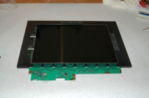
Here’s what the last panel for the projector looks like after being installed into the plywood frame.

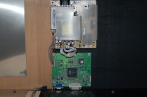
Here’s a pic of the LCD controller and the power supply:

Having all three projectors done is a great step to get completed.

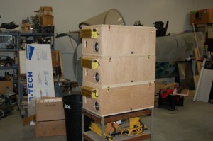
Here’s the “Stack”

I still need to get the supports for those built, but that will have to wait until this coming Saturday.

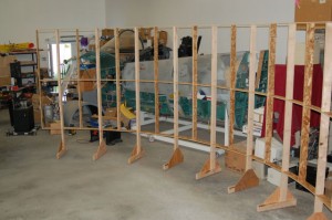
I got six of the screen segment frames assembled last weekend.  This sucker is a lot bigger in real life than it was in AutoCAD…

Each segment is about 63″ wide as measured straight across.  Each 2×4 leg is 95″ long.  It’s BIG.

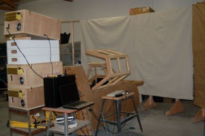
I used some canvas drop cloth as a screen so I could check out a few things.  Here’s what that looked like:

The stupid plasma MM2 is either acting up on me or the “deal” I got on the pots I used on the controls is coming home to bite me.  I’m not sure which…

Until next time!

I _finally_ won the LCD lottery on Tuesday! (My wife referred to it as me finding the golden LCD in the chocolate bar…)

This means that I’ll be able to finish off the third projector on Saturday! I’m really looking forward to that. After I’ve got that finished I’m going to start creating legs for the screen segments.

I still need to decide how I’m going to build the feet – they need to have adjusters on them because of the poor pour quality of my shop floor. I’ll probably go the simple route and use 1/4-20 bolts in to t-nuts for that.

With the exception of being able to change the board ID code function, the Gazoutta 16 firmware is completed and tested. I got the sockets I needed for the bus transceivers so I should be able to fully test the daisy-chain feature as well.

The firmware takes up less than 3k of the available 30k space on the AVR so there is plenty of room for making the board do more – especially since I’ve included pins for an I2C interface on the board itself. There’s an I2C interface library for Arduino that makes that easy to use.