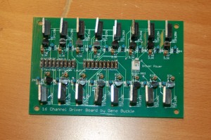
Just before heading off for what I suspect will be a “nom-fest”, I wanted to post a picture of my new 16 channel driver board:
It doesn’t look like much, but this is what I’ll use in the F-15 to drive all the indicator lamps. The board is designed to be directly connected to the Centipede Shield by MaceTech.
There is an error on the board – though. Can you spot it? 😀
Happy Thanksgiving!

The small transistor (bottom left in the picture) seems to be mounted at a different angle to the rest of them. Is that the error?
Nope. 🙂
Good guess though. The problem is actually pretty nasty. I’d forgotten to do a check-print of the board. This resulted in me not realizing that the common lamp power traces were WAAAY too small. If I were to connect lamps to every output on that board and turn ’em all on at the same time, I’d flash the traces to vapor. 🙁 I’m going to do a new revision of the board that will provide for individual power inputs to each channel instead of a single common one.
g.
Instead of redoing the board, and scrapping this one, just dead-bug some hookup wire on the back side. im sure that there is enough lead sticking out the other side to solder some wire to.
G,
Thank you very much for your solution regarding the Hall sensors.
I’m trying to built a simulator for the Jet Ranger 206B helicopter, using the Microsoft Flight Simulator X.
I’m thinking of using the board of a joystick Logiteh Wingman Attack2 for 3 analog inputs. (2 for the stick, and 1 for the pedals) I will have to find another joystick for the collective and power.
For the input switches, I would like to use the little board from a USB keyboard, but I’m concerned that if I use the switch for more than a momentary contact, I can burn the board; if I install a capacitor between the contacts will it solve the problem? (If so, what would be the appropriate value? )
Could you advise if I’m in the right path?
Thank you kindly for your time,
Luis B
You really can’t use a keyboard like that. They’re not designed to handle more than two or three keys pressed at once. I suggest for inexpensive input, you take a look at the Teensy++ board.
g.