DIY Cockpit Project

Articles related to my DIY Cockpit project.

I test printed a model today that I created last week based on SimHQ posting I saw.

Here’s what the solid model looks like:

grip-wip-01jul15-2

The lettering on the face of the grip relates to the control that hinges in the center of the grip – it controls propeller pitch.  It roughly translates to “Coarse” and “Fine”.

Here’s how the print came out:

grip-topgrip-inside

As you can see, the lettering didn’t turn out at all.  This could be fixed in one of three ways.  Increase the size of the lettering (not really practical), print with a smaller diameter nozzle – this was printed on a .5mm nozzle.  A .35mm might be small enough.  Last, you could print it flat and then mechanically engrave the lettering in post production.

My choice would be to do the lettering as a post-production step because the smaller nozzle diameter would dramatically increase the print time of the part.  At 0.5mm it took roughly 2 hours to complete.  With a 0.35mm nozzle, it would be closer to 5 to 7 hours.

The square pockets shown in the second photo are there to take a C&K 8221 tactile push-button switch.  Here’s a photo I shamelessly lifted from Digikey’s website:

c-n-k-8221 switch

The rocking lever that goes on the face of the grip would hit the switches as it is rocked from top or bottom.  I don’t know if I’ll finish the design, but it was a fun design lesson and an interesting print.

This project has been simmering on the back burner for a very long time now.  I only recently got a chance to scrounge up a round-tuit in order to get this thing done.

With the advent of the Arduino hardware ecosystem has come a general bar-lowering for people doing all kinds of projects.  This especially holds true for those of us building simulators of various stripes.  You can find Arudino-based gadgets driving instruments and masquerading as all kinds of little cockpit gadgets these days.

One of the holes in this has been a genuinely easy to use flight control interface based on the Arduino.  Well with the introduction of the MMJoy2 firmware as written by “mega_mozg”, this hole has been filled.

Continue Reading

As I mentioned before, the instrument panel on the Bf-109K4 (and some G models) consists of three parts.  An upper “casting”, a main panel and a blind flying panel.

Since I had the day off today, I took a little time to get some work done before it got too hot in the shop to work.

The original panel mounts that I created aren’t going to work with the current cockpit design, so some months ago, I fabricated some new panel mounting brackets on my 3D printer.

old style bracket

The green part is the original bracket I printed last year when I first started poking at this project.  The small white part is a drill template, which is also 3D printed.

Continue Reading

Some time ago I found a really slick feedback system for DIY cockpit builders – a “shaker” system that pulled data out of the simulator in order to run a motor that would be capable of shaking your entire cockpit.

It’s called the BFF Shaker and can be found here: http://bffsimulation.com/BFF_Shaker.php

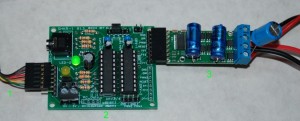
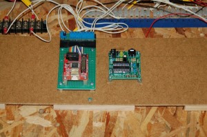
I started my setup with the SHKR-1 board and the 36v15 motor driver from Pololu:

bff-electronics

1 – an FTDI USB/Serial cable from SparkFun.  Note that in order to use this cable with the SHKR-1, you’ll need to invert the TX, RX, CTS and RTS pins.  The documentation for the SHKR-1 talks about the software you’ll need to do this.  This serial cable is how the host software controls the SHKR-1.

2 – The SHKR-1 board itself.  This controller board can drive two of the Pololu motor driver simultaneously.  It also has an output that you can use to drive a “buttkicker” speaker.  (You can use the “buttkicker” alone if you don’t want to build the motor drive system that I show here.)

3 – A Pololu 36v15 motor driver – this takes 24VDC in and allows the SHKR-1 to control a DC motor.

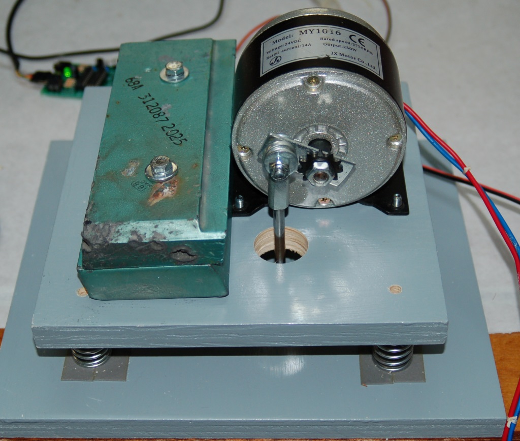
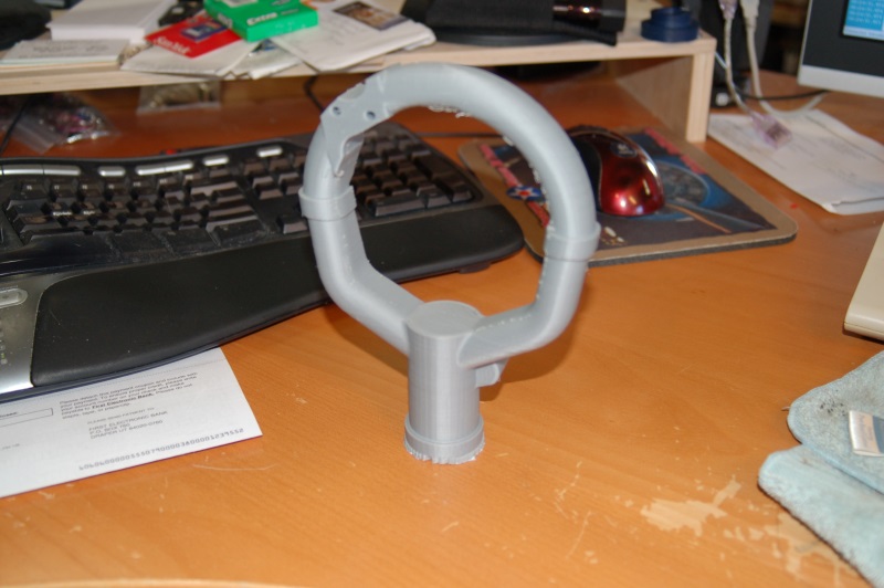
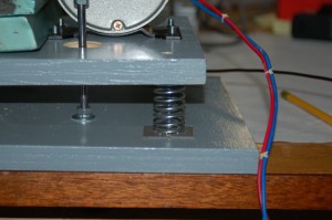
I followed the example of another BFF Shaker builder (Roland) and built a motor platform that rides on four springs.

motor-rig

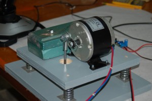
This is a used 24VDC, 250 watt motor.  I bought it off eBay for about $20.  The green blocks next to the motor are a pair of lead C/G weights that I removed years ago from the nose of my F-15C.  There’s about 23lbs of lead there. 🙂

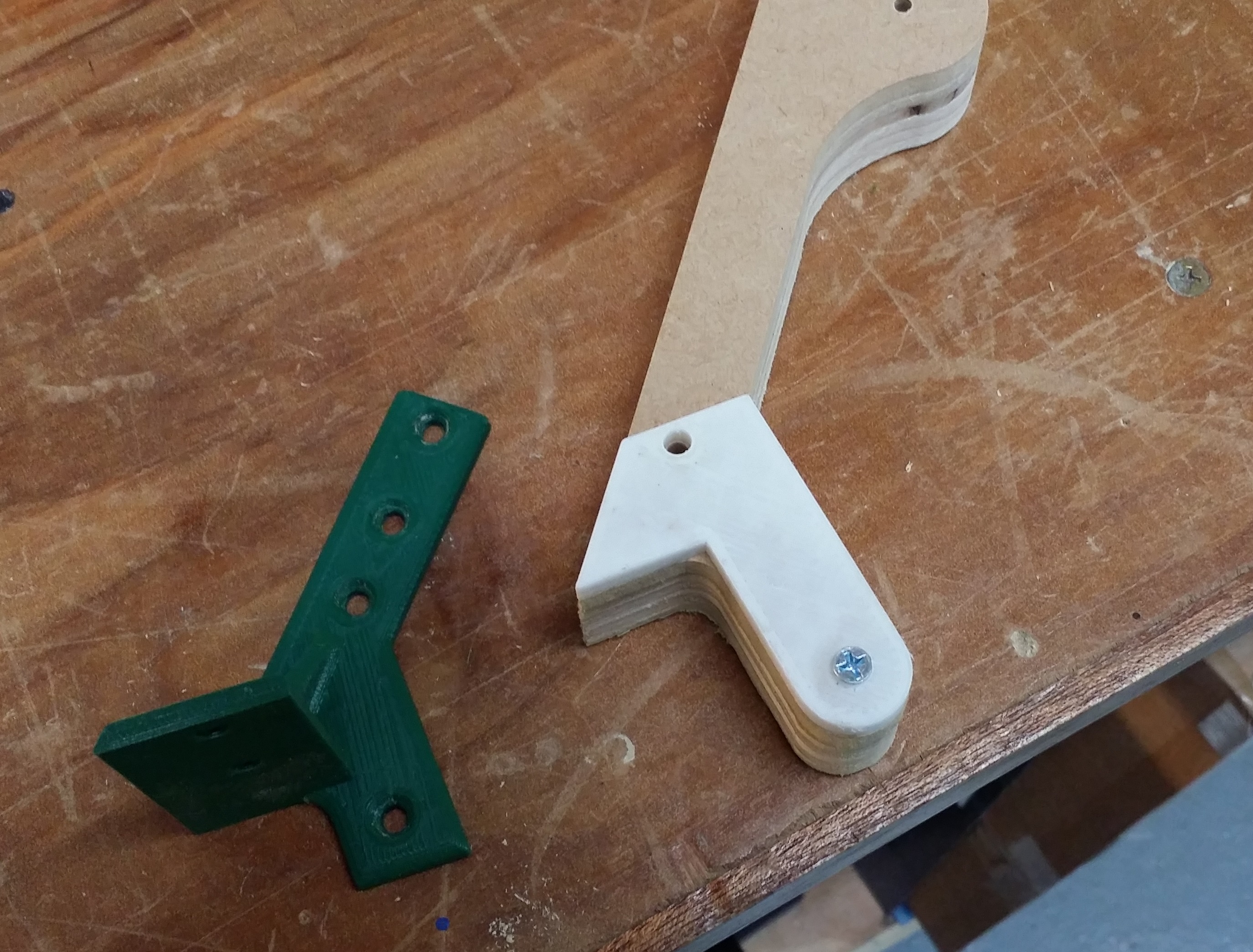
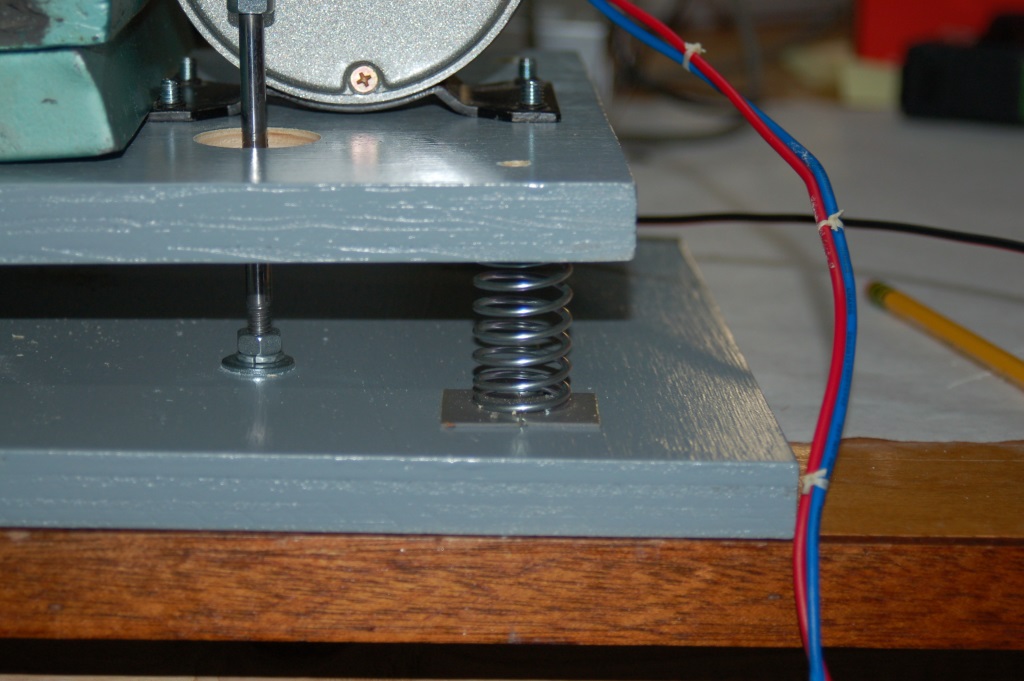
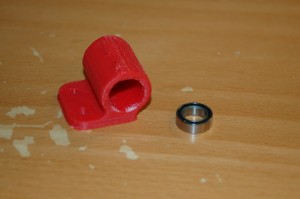
The motor is connected to an offset shaft that is fixed in place to the base platform.  When the motor moves up and down, it’ll transmit that vibration to the rest of the cockpit.  Unlike Roland’s setup, I didn’t insulate the shaker from the rest of the cockpit.  When this sucker is going, EVERYTHING shakes. 🙂

The springs are held in place using 3M VHB (Very High Bond) double-sided tape.  This stuff is VERY strong.  Each spring is rated for about 15lbs of compression force.

spring-detail


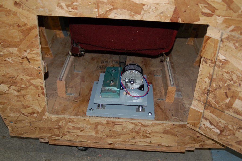
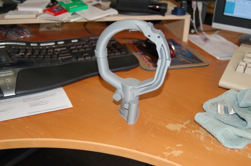
Here’s another shot showing the rig:

motor-rig-2

Here’s a video showing how the whole thing operates:

httpv://youtu.be/jFiU_Qq5iu4

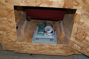
I went ahead and got it installed in the #0 Series One cockpit, right behind the seat:

shaker-installed

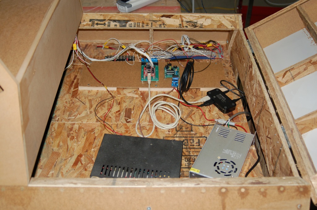
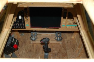
I also spent some time cleaning up the wiring in the front end and got the Plasma-MM2 interface controller properly mounted.

gear-up-frontelectronics close up

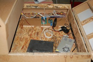
The black box on the left is the 5VDC power supply I use for the panel lighting.  The silver box next to that is the 24VDC power supply that the shaker system uses.

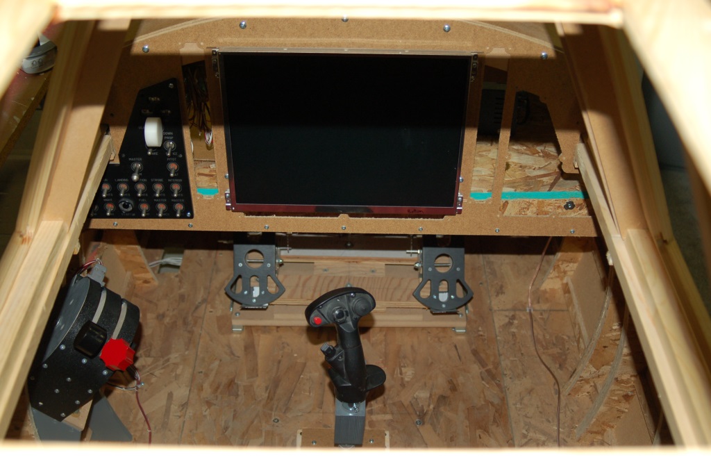
Current cockpit configuration:

current-cockpit-configuration

The shaker system adds a LOT to the whole experience.  It’s a blast to be able to flip on the battery switches, turn on the mags and then mash the starter button and actually FEEL the engine start.  The shaker in the back end really makes that little cockpit rock and roll.  It’s just awesome.  I hope to be able to get some more than once-around-the-field time in it soon.  I need to toss together a screen while I’m waiting for my castAR to show up. 🙂


Some time ago, a buddy sent me an STL file of a Spitfire MkV grip to try to machine on the ShopBot.  I tried it and the most usable result (still wrong) took five hours to machine out of a “billet’ of plywood I made.

I recently finished calibrating my Rostock MAX 3D printer, and decided to give that Spitfire grip another go.

It took 11 hours, 17 minutes and 7 seconds to print.  It consumed 35.6 meters of 1.75 silver ABS plastic filament.  There’s a few areas where the overhang is too great and it messed up a tiny bit, but overall I’m very happy with the result!

Back of the grip

Back of the grip

Front of the Spitfire grip

Front of the Spitfire grip


Front side, cleaned up

Front side, cleaned up

Back side, cleaned up

Back side, cleaned up

The grip is amazingly strong and doesn’t warp at all when you twist on it.  The grip was printed using KisSlicer as the slicing software and uses a 25% infill. (that means that 75% of the interior space in the model is just air).

First, the video!
httpv://www.youtube.com/watch?v=o7tJaJJbRkc

A regular Arduino really drive things that have high power requirements or need a voltage higher than 5vdc. In order to run the real displays in the F-15 that use incandescent bulbs, I developed a special board that would allow me to drive up to 16 channels per board, up to 60vdc at round 8A per board.

The Centipede Shield by Macetech provides 64 I/O channels – each of the 64 channels can be configured for input or output. In this context however, I’m using the board as strictly an output device.

Here’s the code that the Arduino runs: centipede_firmware

For those that want to build the driver board, I’ve zipped up the Eagle PCB files for the board – the zip file INSIDE the zip file is “gerber” data that you need to supply to the board house if they don’t natively process Eagle PCB files.

TIP125-Board-v2
Enjoy!

For a while now I’ve wanted to replace the crappy, noisy pots that I’d used in my Jentron MK2 gimbal that was in the 109F/X #0 cockpit.  They were so bad that it was impossible to use the gimbal for flight at all.

The best way to replace a mechanical potentiometer is to use a hall effect device.  This is essentially a sensor that will output a 0 to 5v signal based on the position of a magnet.  I’m using the Allegro 1302 for this project.  It works very, very well and can be a direct replacement for any three wire pot installation.

My design uses a 7/8″ (22mm actually) bearing with an 8mm center bore.  The center bore allows you to use a “traditional” Bic pen body as an input shaft.  You can press the body segment into the bearing and it won’t be coming out any time soon!  You can purchase the bearings here: http://www.vxb.com/page/bearings/PROD/SB/Kit1063

I installed the pen body into the bearing and then glued a pair of 1/4″ square neodymium magnets (oriented NS-pen-NS) to either side of the pen body with some thick Cyanoacrylate glue.  Works great!

In order to be a direct replacement for the pots, I needed to add similar control arms to them.  I did this by laser cutting a press-fit back plate that I threaded for #4-40 screws.

Continue Reading

Just before heading off for what I suspect will be a “nom-fest”, I wanted to post a picture of my new 16 channel driver board:

It doesn’t look like much, but this is what I’ll use in the F-15 to drive all the indicator lamps.  The board is designed to be directly connected to the Centipede Shield by MaceTech.

There is an error on the board – though.  Can you spot it? 😀

Happy Thanksgiving!

The world’s first amateur built cross-cockpit collimated video display system:

This is a 60 degree wide by 40 degree high spherical section collimating mirror.

More information can be found here: http://www.diy-cockpits.org/coll/collimated_display.html

Until yesterday (11/20/2010) this kind of thing was the sole domain of multi-million dollar commercial flight simulators.  Not. Any. More. 😀

Thanks all!

g.