I finally found a spare moment to make some adjustments to the pitch & roll gimbal I designed for the Bf-109K4 project.
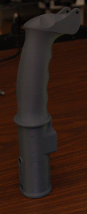
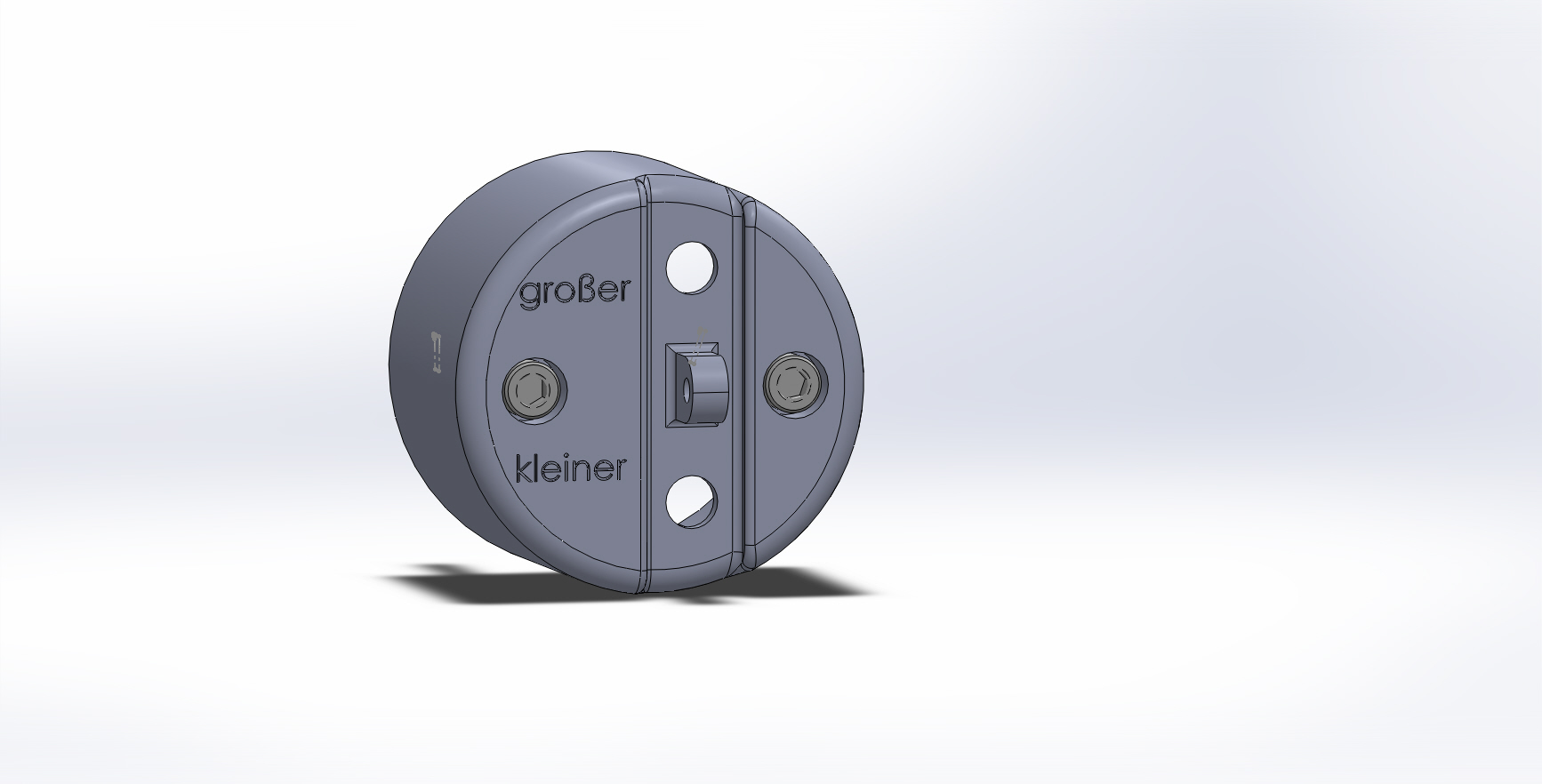
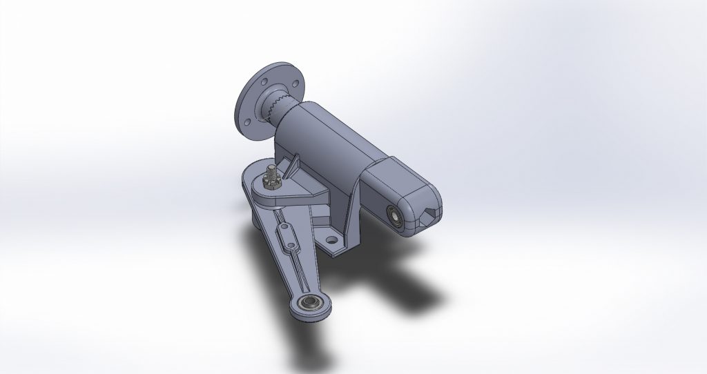
Below is a rendering of the 2nd revision of the major components in the pitch & roll axis assembly. The one shown in the later photos is revision 5. This whole gimbal assembly was designed based on photographs I obtained from a number of different Bf-109 revisions, so it’s kind of a “kitbash” of features from the E, G, and K models. Good enough for sim work. 🙂
The existing gimbal used a pair of 608ZZ skate bearings to support the roll axis parts. This was fine, but wouldn’t permit me to tighten the “stack” of components that made up the roll axis. If you apply a side-load to a 608ZZ skate bearing, you’ll eventually tear up the bearing. They’re only really designed for radial loads.
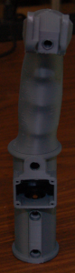
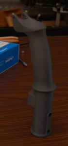
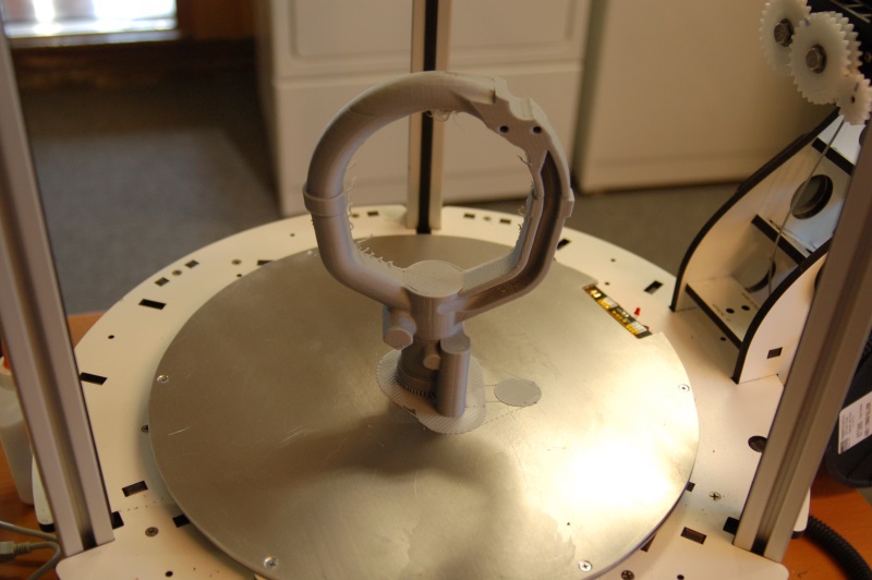
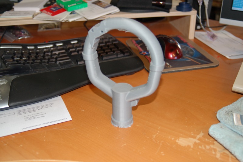
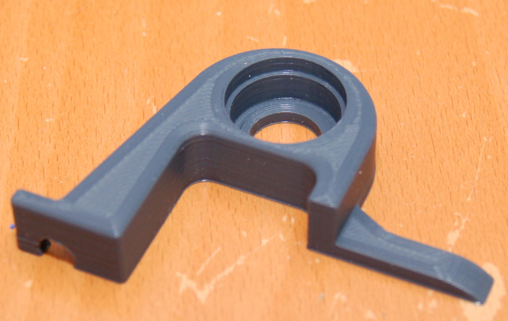
Here’s what the front of the original gimbal design looks like:
I needed to tweak the design a bit in order to accommodate the thickness of the thrust bearing stack I’m using. The stack is 4mm thick, (washer, bearing, washer), so I needed to push the skate bearing back into the body of the “casting” by 4mm.
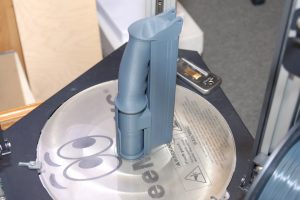
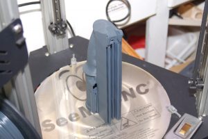
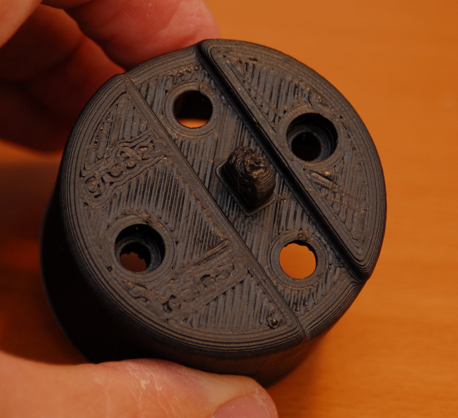
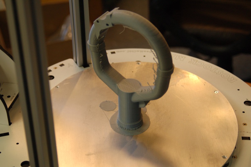
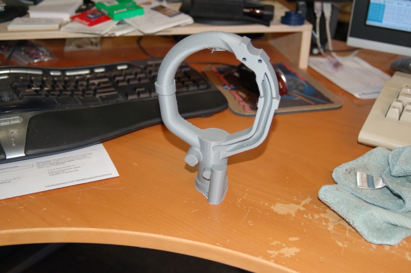
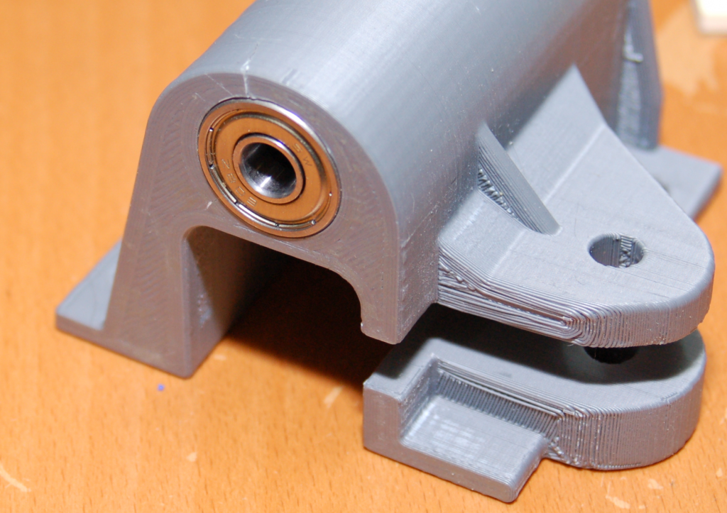
I didn’t want to spend the 13+ hours it was going to take to reprint the whole part, so I “sunk” the whole part into the build plate, leaving only about 15mm sticking above the print surface. This allowed me to print a sample of the gimbal in about an hour. Here’s the revised example:
As you can see, there’s a step where the thrust bearing will rest, over the top of the skate bearing.
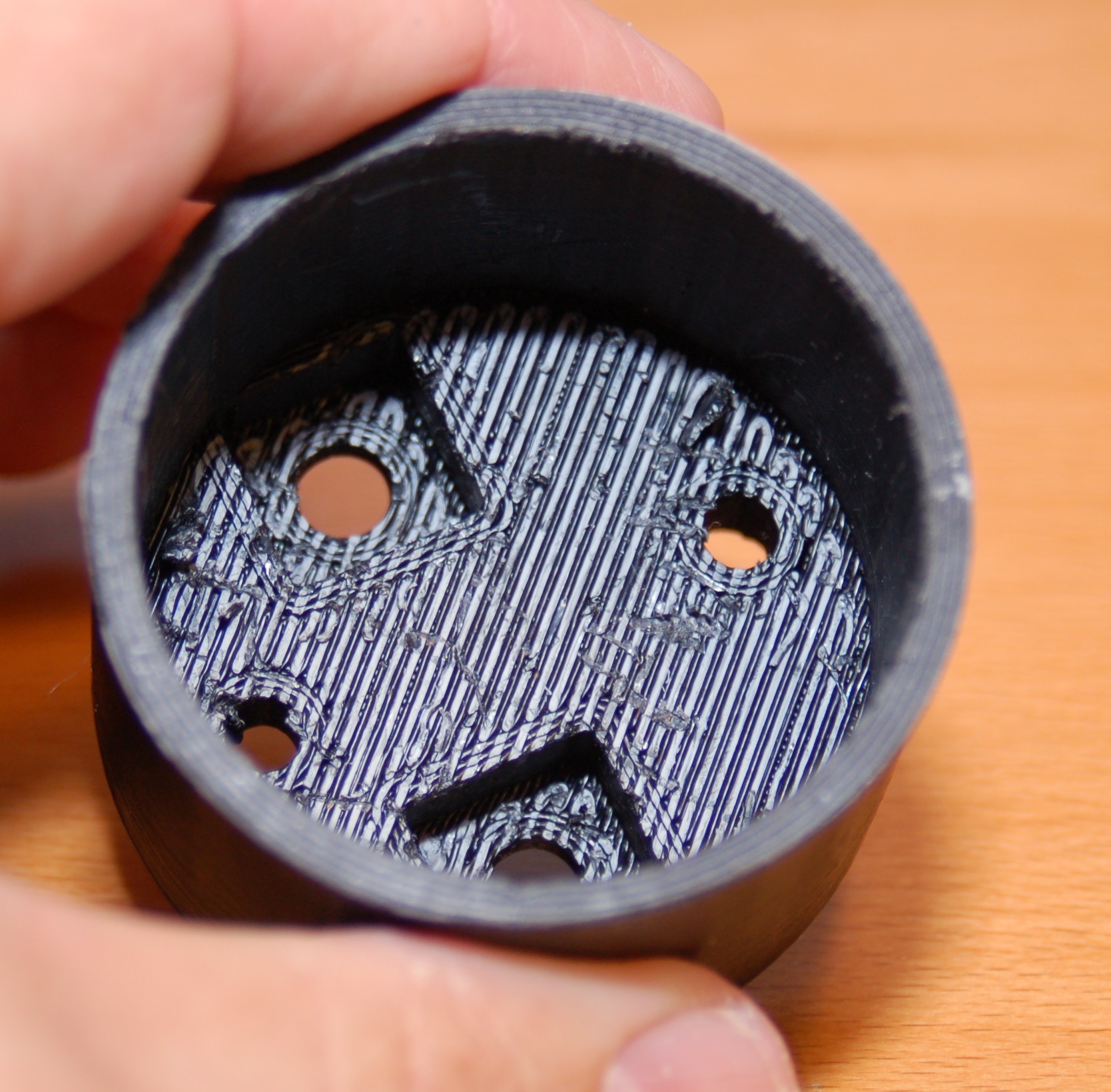
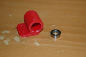
First we start off with the skate bearing:
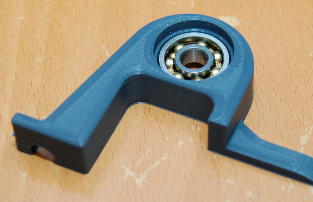
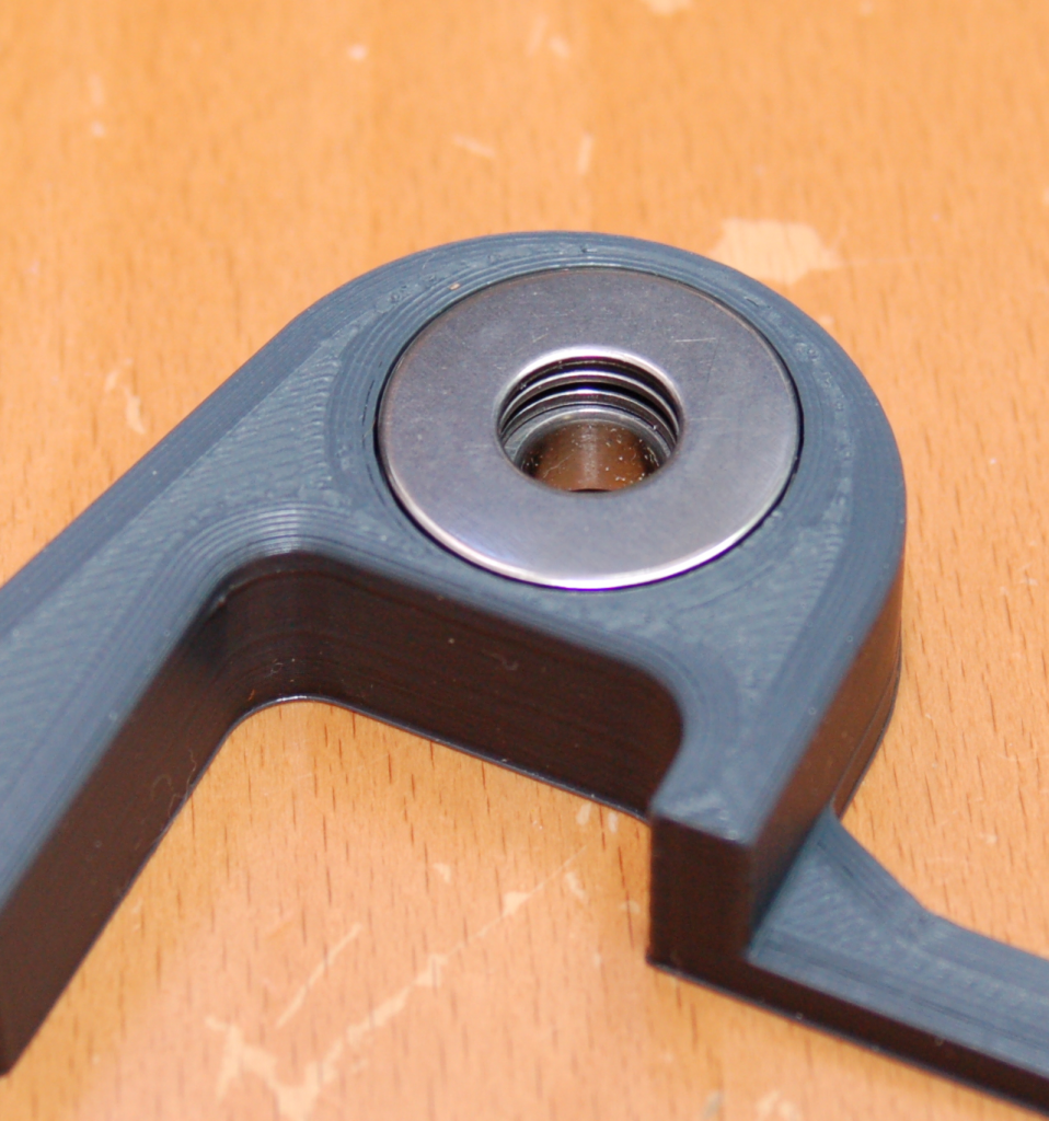
The bearing is just a little loose in the pocket – that’s fine for this application. Next, the first thrust bearing washer goes in.
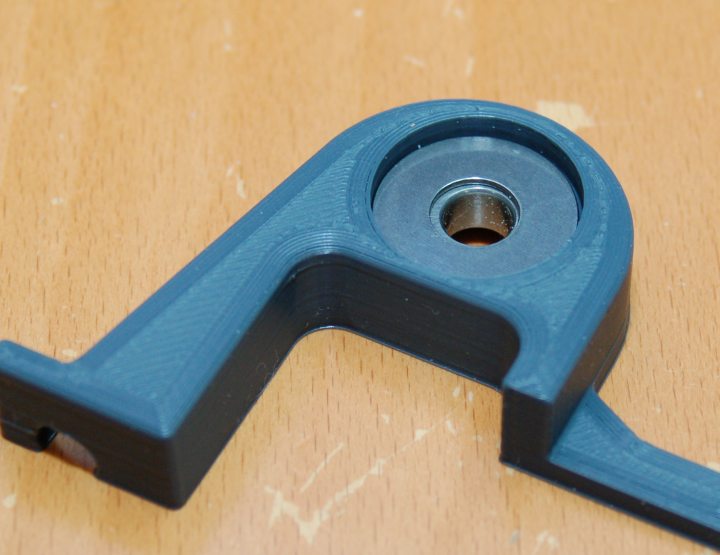
Next comes the thrust bearing itself. It’s made up of 13 needle bearings. I chose this type of thrust bearing over a tapered thrust bearing due to cost & size.
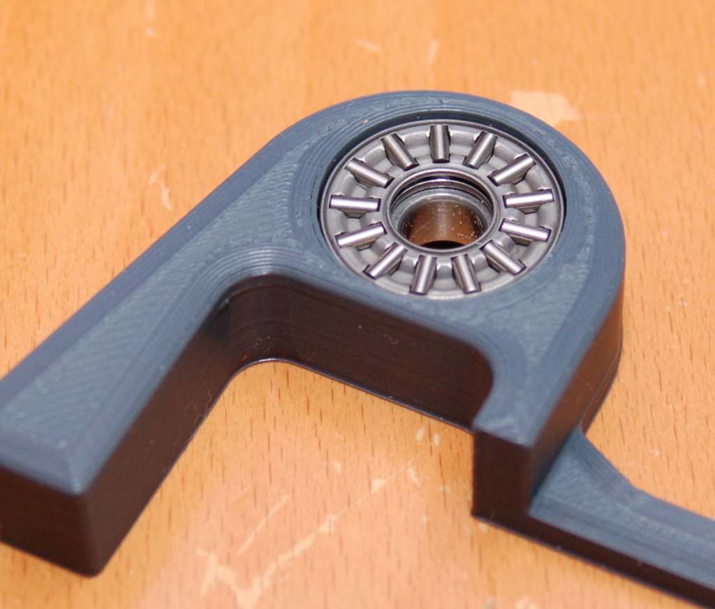
Finally, the last thrust bearing washer is installed.
I’m using a 5/16″ bolt as the roll axis shaft inside this gimbal and the addition of this thrust bearing, plus one at the other end, will allow me to fully tighten the whole assembly. Now I won’t have to worry about it slipping or crushing the races in the skate bearings.