DIY Cockpit Project

Articles related to my DIY Cockpit project.

..are now DonationWare!

You can download the 386MB ISO from here.

There’s no difference in the content between the commercial edition that I was selling and this one, with the exception of the cost.  It’s purely donation-ware at this point.  Pay what you feel it’s worth to you!  From nothing to One Beeeeeelyun Dollllaarrrs! *laughs*

This edition contains three supplementary drawing sheets that were not included in the original release, including parts for a sub-deck in the front of the cockpit and new parts for flatter fuselage sides that are easier to skin.

Thanks All!

(Read the prior blog entry to this for details on the projector stands)

After completing the projector stands it was time to finally use the damn things! 🙂

Because of the flexibility of modern games and the popularity of “triple head gaming”, new games like Need for Speed: Shift support the resolutions that can be found using a TripleHead2Go.  In my case that’s 3072×768 because I’m using three 1024×768 projectors.

My friend Dave is a nut for this game and I finally understand why. It’s insanely fun to play on a 180 degree wraparound display. 😀

Continue Reading

As of yesterday, (14Aug10) the new projector stands are finished and they turned out great!

I got this idea after the last setup I’d done last month – it turns out it works just as well as I’d hoped.

The projector stands were built from 3/4″ plywood and 2×4’s for the legs.  The support box is designed to hold a 3.5″ PVC pipe that acts as the actual support for the projector.  This allows the projector to rotate left and right very easily.  The height of the projector can be adjusted using a “step” pin that the PVC can rest on.  The series of holes you’ll see in the sides of the support box are for those pins.

Continue Reading

The 16 channel output board I’ve been working on is now finally completed!

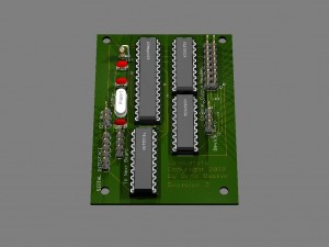
This is a render of the final version of the board – this version has been sent off to a PCB house for manufacture (blank boards only):

This board will provide 16 channels of output, up to 500mA per channel at up to 30VDC.  The board costs about $20 in parts to make.  I’ll likely sell any spare blank boards I have for $10 each.  I don’t offer them as an assembled device or as a complete kit.

The link below is for a zip file that contains everything you need to build your own Gazoutta16 board, including the schematics, board layout and the firmware source code.  It’s based on the Arduino software stack (http://www.arduino.cc)

gazoutta16_project

If you have any questions, you’re welcome to contact me at the address given in the readme.txt file in the archive file listed above.

Thanks!

Short video:

httpv://www.youtube.com/watch?v=bPkPnSrUbiw

The screen has a diameter of 15 feet with a usable circumference of about 30 feet.  Like its predecessor, the new screen is 78″ tall.

The glue still needs to dry before I do any finish work on it.  I’m going to either hit the local fabric store for some white muslin, or Home Depot for a couple of more drop cloths.  I haven’t decided yet.  Eventually, I’ll pony up for commercial grade screen material, but that will have to wait for funds to be available. 😀

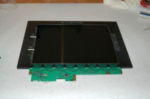
Here’s what the last panel for the projector looks like after being installed into the plywood frame.

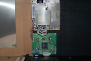
Here’s a pic of the LCD controller and the power supply:

Having all three projectors done is a great step to get completed.

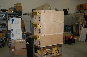
Here’s the “Stack”

I still need to get the supports for those built, but that will have to wait until this coming Saturday.

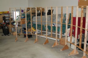
I got six of the screen segment frames assembled last weekend.  This sucker is a lot bigger in real life than it was in AutoCAD…

Each segment is about 63″ wide as measured straight across.  Each 2×4 leg is 95″ long.  It’s BIG.

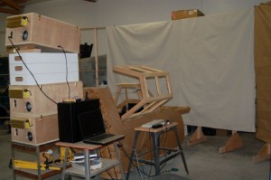
I used some canvas drop cloth as a screen so I could check out a few things.  Here’s what that looked like:

The stupid plasma MM2 is either acting up on me or the “deal” I got on the pots I used on the controls is coming home to bite me.  I’m not sure which…

Until next time!

I _finally_ won the LCD lottery on Tuesday! (My wife referred to it as me finding the golden LCD in the chocolate bar…)

This means that I’ll be able to finish off the third projector on Saturday! I’m really looking forward to that. After I’ve got that finished I’m going to start creating legs for the screen segments.

I still need to decide how I’m going to build the feet – they need to have adjusters on them because of the poor pour quality of my shop floor. I’ll probably go the simple route and use 1/4-20 bolts in to t-nuts for that.

With the exception of being able to change the board ID code function, the Gazoutta 16 firmware is completed and tested. I got the sockets I needed for the bus transceivers so I should be able to fully test the daisy-chain feature as well.

The firmware takes up less than 3k of the available 30k space on the AVR so there is plenty of room for making the board do more – especially since I’ve included pins for an I2C interface on the board itself. There’s an I2C interface library for Arduino that makes that easy to use.

Well the last post was “Projectors! Projectors! Projectors!”  This one was nearly called, “Projectors! Projectors, Proj..wait, what?”

When I was first planning for the projectors, I did some research on what kind of LCD panel would be both affordable and suitable.    This led me to a web forum run by Lumen Lab – they at one time were a great resource for parts on building a DIY projector – they’re now just a forum with a store that sells robot parts.  Go figure.  Anyway, the research I did on the forum led me to something I wasn’t aware of.  “FFC problems”.

It turns out that FFC stands for Flat, Flexible, Cable.  It turns out that many LCD manufacturers have a small (and I mean _SMALL_), thin cable that joins the circuit board along the top to a circuit board along the side.  This is fine when it’s being used for its intended purpose.  The problem is that in order to use the LCD in a projector, you’ve got to move both of those circuit boards out of the way so they don’t block the incoming light or the outgoing image.

Continue Reading

…but before that…

I replaced the Plasma V2 with a Plasma MM2 that I had.  Turns out that the P2 was the core of all my controllability problems.  Once I installed the MM2, it was a whole ‘nuther ballgame.  No more crazy spikes or sluggish control inputs.  It was pretty damn nice actually. 🙂

Here’s the board I put together in order to interface the MM2:
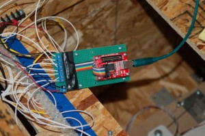
What kills me is that this device is no longer available.

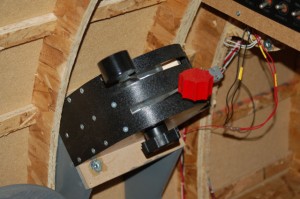
Another change I made was to the return springs that were in the pitch axis mechanism.  The original springs weren’t up to the task with the amount of weight in the grip & interface box.  The stick would stay where ever I let go of it.  The springs I use are compression springs that are 2″ long and made from .072″ diameter wire.  I changed to a 2.50″ spring made of .080 wire.  This made a big difference for a small change.  The pitch axis now returns to center the way it should.  However, the feel is still a bit weak so I may change that to an even stiffer spring.

Ok, now back to the title of this entry…

I ordered three projector kits on the 31st of December.  After an agonizing wait they were finally shipped.  Here’s some of the parts:
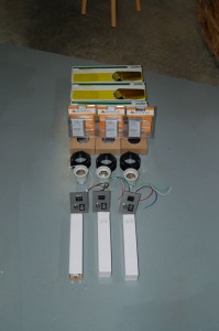
The kit consists of optics (220mm & 330mm fresnel lenses and a 330mm “triplet” output lens), power panel, 400W Metal-Halide lamp (that the 12 year old in me has christened The Photon Phallus. *snickers*), Mogul base for the lamp, temperature controller for the fan, a fan and a 400W ballast for the lamp.  All of this neat stuff is available from DIY Projector Kits (http://www.diyprojectorkits.com).

Be warned, the plans (at least for the one I have, the S-15) are VERY, VERY, VERY vague.  If you get one and have questions, either see my build thread on the site (“geneb’s triple threat”) or email me directly.  My build thread will do what it can to rectify the captionless pictures that comprise some of the documentation. 😀

On the 23rd, I spent the day doing maintenance work on the ShopBot, including adding a 1/32″ gasket to all the vacuum zones.  The gasket drastically improved the performance of the vacuum hold down system.  I then got all the parts cut for the projector cases.  I used 18mm (3/4″) Baltic Birch.

Here’s the first of two sheets that were cut:
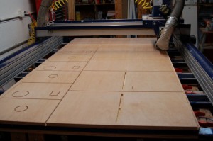
The parts in the foreground with the long slot in the center is the projector top.  The slot is the air intake for the lamp cooling fan.  It draws air in-between the “cassette” that holds the 15.4″ LCD panel and the cassette that holds the collimating fresnel.  You’ll see pictures of these things in the coming days.

Here’s the stack of parts that resulted from yesterday’s run:
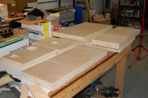
The next steps are to mark & drill the case parts for the pocket screws I’m going to use for assembly and make the LCD and fresnel cassettes….

To hold you over till next time, here’s a video I shot of the beta version of the avionics system I’ll be using in the cockpit:

httpv://www.youtube.com/watch?v=1X69mIBtyu0