| Here's
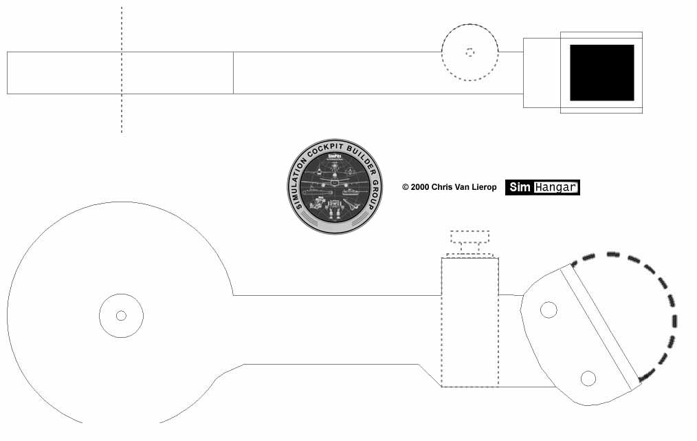
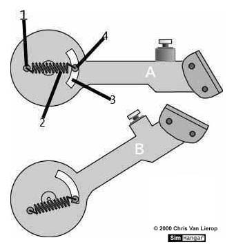
a way to add some tension to the movement of the handle, as well as locking
it in the endposition
1 = A pin
connected to the gear handle
2 = A tension-spring
3 = Carved
out shape in the gearhandle
4 = pin
that moves in the carved out shape and is attached to a fixed part independently
of the gearhandle
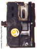
In picture A
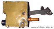
the handle is in the middle position. In picture B it is in the up position.
In picture B the spring has shortened in length because the two pins have
moved closer to eachother. This is how the spring keeps the handle locked
in this position.
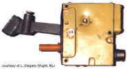
The same thing
applies to the handle being in the down position... The spring also makes
for some 'tension' in the movement, 'forcing' it to the end positions. |