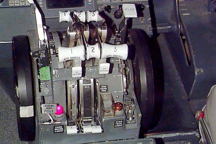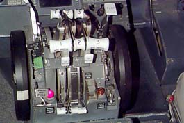
The 727 throttle quadrant. Here you can see, from
left to right:
Manual stab trim wheel. This can be used to adjust
the horizontal stabilizer trim of the aircraft if the electric controls
or the stab trim motor shoud fail. There is a manual handle that
can be rotated 90 degrees out to allow the pilot or co-pilot to manually
ajdust the trim. These trim wheels normally move at a high rate of speed
when the pilot or co-pilot command a trim change using the yoke mounted
trim switches.
Stab trim position indicator. This scale tells the
pilots where the stab trim is currently positioned. The green band
indicates the safe trim range for take-off.
Speedbrake handle. This handle deploys the speedbrakes
on the aircraft. The speedbrakes deploy by "splitting" the upper
portion of the wing flap up, thus creating more drag to slow the aircraft
down on landings, or whenever there is a need to slow the aircraft down
in flight. The forwardmost position is "off", one notch to the rear
is "Armed" and then there are more rearward steps for each amount of speedbrake
deployment needed.
Parking Brake. This is a small metal lever that
is pulled upwards to lock the brakes. You shove the toe brakes (on
the rudder pedals) as far down as they will go and then lift the lever.
The red light will illuminate to indicate the parking brakes are active.
To release them, you just depress the toe brakes again and the lever will
automatically drop.
Throttles & Thrust Reversers. These three handles
(marked 1 - Auto Throttle, 2, 3 - Auto Throttle) are a dual function mechanism.
The long handles extending forward control the thrust reversers and they
have three positions. Retracted, Armed and Extended. To arm
the thrust reverser, you bring the handle back until it's nearly vertical.
To extend the reverser, you bring the handle rearward. They will
not move into the extended position unless the throttle arm is in the Idle
position. When the reverser extends, a 2 peice metal clamshell device
pops away from the rear of each affected engine and closes around the rear
of the engine, directing the engine thrust a bit forward and avove and
below the center line of the engine. This is used to slow the aircraft
down during the initial moments of touchdown. If the pilots were
to stand on the brakes without using the thrust reversers first, the brakes
would quickly heat up and catch fire.
On the #1 and #3 throttle arms are the "Go Around" switches.
When the aircraft is in an autopilot controlled descent to landing, pressing
either one of these switches will command the autopilot to increase the
thrust by automatically moving the throttles forward and it will also command
some up elevator.
Fuel cocks. Right below the throttles are the Fuel
Cocks. These three levers control whether or not each of the three
engines gets any fuel. In this image, they're in the down or "Cutoff"
position. They would need to be moved into the open or "Idle" position
to allow the engines to be started.
Stab Cruise Trim. Just to the right of the fuel
cocks is the Stab Cruise Trim switch. This switch is used to adjust
the horizontal stabilzer trim while the aircraft is in flight. The
reason it's there is because it moves the trim tabs at a MUCH slower rate
than the yoke mounted switches do and allows the pilot a finer degree of
control than could be achieved using the yoke mounted trim switches.
To the right of the switch is an orange lamp. This is illuminated
whenever the trim system is activated.
To the right of the Stab Cruise Trim switch is a pair
of metal levers that affect the trim system in some way, but I don't recall
their exact function. If anyone can provide insight on these, I'd
appriciated it. *g*
Update! [05/05/00]
Douglas Snow informs me that:
"As for the stab trim paddle switches - they are the
power switches to the powered trim system. Move them to CUTOUT and
the manual wheels come into play."
Flap Lever. This controls how far the leading and
trailing edge flaps are deployed. Each position has a notch that
requires the lever to be moved in a "U" shaped pattern. This prevents
accidental deployment of the flaps as well as accidental changes in degree
of deployment.