This is the primary video display from the 757 instructor
station. Unfortunately, the contents aren't really visible at all.
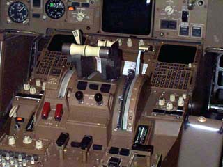
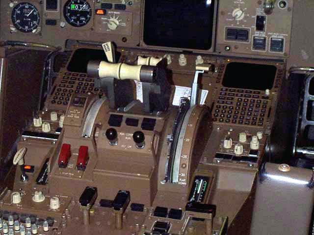
This is the center console of the 757 simulator.
The handles are, from left to right:
Speed Brake
Engine #1 Throttle
Engine #2 Throttle
Flap Lever.
The two toggle switches below the throttles are the fuel
cutoff switches.
To the bottom of the flap lever arc you'll notice a black
panel with a white line going about halfway down the middle with a green
strip next to it. This is the horizontal stab trim indicator.
The green line indicates the safe range for takeoff. Two things I noticed
when I took this picture. One odd and one amusing. The odd thing
is that there doesn't seem to be any manual way of adjusting stab trim
like there were in some of the earilier Boeing designs. The amusing
thing is that it seems that the APU fire handle has been activated.
Makes you wonder what that instructor put the previous crew through, doesn't
it? The APU fire handle is the rectangular shaped knob right below
the right hand stab trim indicator. The engine fire handles are mounted
somewhat in line with the APU fire handle, in alignment with the engine
throttle handles.
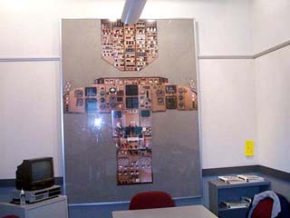
This is one of the training devices used at the facility.
It's primarily used for familiarity and to illustrate concepts that the
instructor is trying to teach.
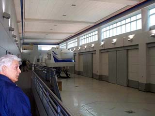
This is the long view of one of the more unoccupied simulator
bays. The white squares on the right are the 20 foot by 20 foot doors
that were used to move the simulators into the buildings. As you
can see by looking at the floor, there is room for two more simulators
to be installed.
The gent to the right is my father-in-law, Edwardo Pina.
He used to be a Boeing Exec. Very bright dude. I'll be posting
a paper he wrote on the system logic to be used in collision avoidance
systems. (Like I said, he's a very bright dude. :) )
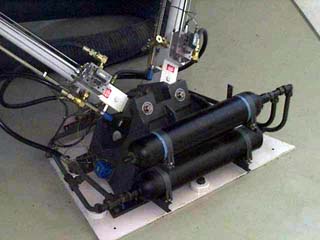
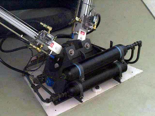
Here is a closeup view of the accumulator/buffer tanks
that are required by the hydraulic system. It's primary purpose is
to balance the pressure in the system and to prevent wave shocks from travelling
back to the pump. They're filled with nitrogen gas - this was done because
it won't react chemically with the hydraulic fluid and the metal parts.
Nitrogen gas will also not spontaneously combust the oil when it's hot
and under pressure.
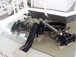
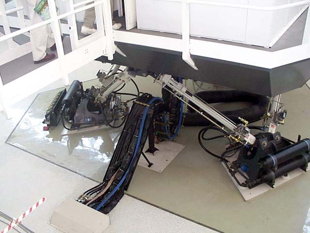
Here is yet another view of the motion base. The
cable run coming from the rear goes into the floor, through a fire barrier
and into the computer room and the pump room, respectively. The main
hydraulic feed hose is about 4 inches in diameter and runs at a pressure
of approximately 1500lbs per square inch or greater, depending on the simulator.
A catestrophic failure in any of the hydraulic lines will result in a painful
death or maiming if you're too close when it goes. Keep in mind that
any fluid under this kind of pressure will cut through steel, so a human
body isn't much of an impediment.