 *Note: Those of you who read my
previous
report on FlightSim.Com, should skim through the entire report since
many changes have been made based on the multitude of questions and feedback
people around the world have supplied.
*Note: Those of you who read my
previous
report on FlightSim.Com, should skim through the entire report since
many changes have been made based on the multitude of questions and feedback
people around the world have supplied.
 Foreword: Foreword:
This is a report
which shows how to cut the cost of a homebuilt flight simulator by many
hundreds of dollars through the use of keyboard interfacing. For anyone
who hasn't had the pleasure of gazing upon Kev Saker's fantastic homebuilt
flight simulator, you should definitely click
here and check it out.
Introduction
By inspiration
from the flightsim genius Kev Saker, I decided to try a brief suggestion
given by him in one of his articles, on FlightSim.Com, as it relates to
hard-wiring the entire simulator to a keyboard card and it worked. By doing
this, you will need NO solenoids or EPIC cards whatsoever. The cost of
the entire electrical interface (not counting wiring or switches) is around
$15 versus the EPIC card method which could cost hundreds or even more
than $1000. I will attempt to describe the concept behind this new electrical
interface so that you can use this technique with any aircraft you'd like.
Since the last
report, digital images have replaced the more primitive hand drawings in
hopes of clarifying information.
The Interface
If you plan
to use indicator lights, please do not put them on the same switches and
lines as the keyboard card or you will most likely blow the keyboard card
out. Figure E1-4 (near the bottom of the page), shows a proper technique
for connecting indicator lights without disturbing the keyboard card. E1-4
is a more complex component, so refer to figure 1-2 to see the simplified
version. Remember that the keyboard supplies its own power supply so you
will not need to worry about any manual power supplies unless you intend
to use indicator lights.
Materials
To construct
the electronic interface for your simulator, you will need a keyboard,
switches and lots of wire. The type of each of these parts that you will
need is as follows:
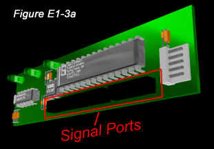
Keyboard: I would advise
that you use the AT style 5-pin keyboard rather than PS/2. If you have
a PS/2 style port on your computer, you can buy an adapter from most computer
accessory retailers for less than $5. The reason I would advise that you
use this style of keyboard is that you can desolder the two signal ports
on the card and replace them with your own wire (This is a hundred times
easier than it sounds). Everything should work exactly the same using a
PS/2 keyboard though, so if you would rather use one, go for it.
Switches: Only momentary
buttons should be used in conjunction with the keyboard card, or else you
will get a key repeat whenever you activate a button. A recent exception
has been discovered and is discussed near the end of this page.
Wires: Try not to use
wire too thin or you may chance the wire melting or overheating. 20 - 22
Gauge is optimum. The wire you buy should be solid (not stranded).
8-Position Barrier Strips:
These strips allow you to instantly connect a wire to an extension wire
on the keyboard card using only a small screw driver. They also prevent
the exposed ends of each wire from touching thereby preventing signal crossovers.
Constructing The Interface
You will now
need to strip the keyboard down until you are left with three transparent
sheets, an electronic keyboard card, and a long connector cord. Do not
remove the plastic sheets yet because they play an EXTREMELY important
part in this interface. The part of the keyboard that you will need to
be concerned with are the two slots that the transparent sheets are connected
to. By 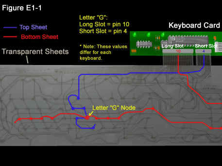 connecting
a wire from the "short" slot to the "long" slot, you can create any keyboard
output that you'd like. Each keyboard has different signal requirements
(slot combinations) and that is why you'll need the transparent sheets
to determine which pins on each slot control each letter. You may also
want to keep the keypad so that you can determine which node on the sheets
corresponds to the letter you want. connecting
a wire from the "short" slot to the "long" slot, you can create any keyboard
output that you'd like. Each keyboard has different signal requirements
(slot combinations) and that is why you'll need the transparent sheets
to determine which pins on each slot control each letter. You may also
want to keep the keypad so that you can determine which node on the sheets
corresponds to the letter you want.
The sheets work
like a schematic and work as follows: If you want to create the letter
"g", you would directly line up the transparent sheets and place them in
an upright position. Now locate the node which corresponds to the letter
"g" as in figure E1-1 (place the sheets on top of the keypad to help locate
the node if needed). Now, on the top sheet, locate the node that you just
marked/remembered for the letter "g" and follow the line that it is on
until you reach the signal port (long slot or short slot) on the keyboard
card as in figure E1-1. Now, note which pin the line ended at, and repeat
this process for the bottom sheet. These two values represent the signal
required to create the letter "g". The shortcut method to this is to simply
cut a short wire and connect it between each port and record on a sheet
of paper what letter was produced. In other words, bridge the wire between
port 1s, and 1L, and record what letter is produced, then bridge the wire
between ports 1s and 2L and record the letter produced... etc. You should
then have a chart of every key on you keyboard and what letter it produces.
Of course You will need to connect your keyboard card to your compuer to
do this.
Shorthand
This keyboard
shorthand speeds thing up a bit in recording signal requirements and may
be seen a bit on my site. It works as follows:
1s, 2L
1 - A port number
s - symbolizes
that the coefficient represents a port on the short slot
2 - A port number
L - symbolizes
that the coefficient represents a port on the long slot...
So the values
on the diagram below could be summarized as 4s, 10L
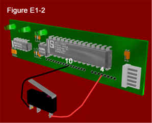
Now to send the
signal for this key to the computer, all you need to do is take a wire
and place one end in the pin you marked on the short slot, and place the
other end in the pin you marked for the second slot as in figure E1-2 (once
you remove the transparent sheets). As you can see, Figures E1-1 and E1-2
are exactly the same except one uses the transparent sheets, and the other
uses wire and a micro (lever) switch, although any momentary push button
will work. That's it. You have just created the letter "g". It is a hundred
times easier every time you do it and you can now repeat this process for
each switch and button you plan to use. Now, you may safely remove the
transparent sheets. The middle sheet, that has nothing on it, is useless
and can be discarded at your own leisure unless you plan to reassemble
the keyboard. There are a few major points that I must make in regards
to the interface before you begin adding a lot of buttons.
Because many
letters will use any given node, and the nodes are very small, it will
be necessary to connect extensions as shown in figure E1-3c. These are
nothing but strips of wire with one end connected to a pin and the other
end left free or connected to a terminal/barrier. This will allow you to
add as many wires to each slot as necessary. Whenever you want to connect
a switch to a particular pin on the keyboard card, you will instead connect
it to the corresponding extension wire or terminal. If you use a terminal
strip, you will only need to screw the wire into the proper terminal, but
without terminals you will have to fire up your soldering iron every time
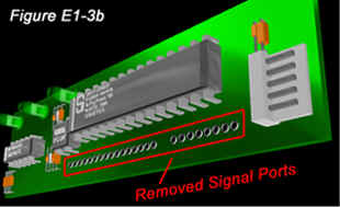
you want to attach wires. John Hastie
from Australia provided a very helpful technique in which you remove the
signal ports (the long and short slots that the transparent sheets were
connected to) in order to allow the easy connection of your extension wires.
To do this, flip the keyboard card over and locate the soldered pins directly
beneath the long and short slots. Desolder all pins directly beneath the
two slots, and remove the two connection slots. Then proceed to solder
in your own extension wires as shown in figure E1-3c.
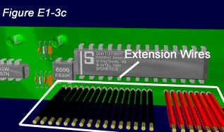 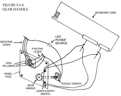
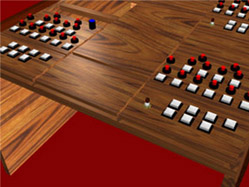
Figure E1-4 shows
how the landing gear panel would generally look using indicator lights,
and using Kev Saker's gear switch setup. By connecting the up and down
micros to the proper extension wires on the keyboard card, you can easily
create a working landing gear lever. You can add indicator lights to the
panel as well by connecting the gear lever to a SPST (Single-Pole Single
Throw) switch and connecting each of the indicator lights to extension
wires from that switch. Just remember to keep the indicator lights' power
supply off the same lines as the keyboard card.
Creating Multiple Signals With One Switch
A good friend of mine and fellow
flightsim builder
Peter
Cos recently obtained a great schematic for creating multiple button
presses with one switch. We call the schematic the Popescu circuit in honor
of his father in law who created it for us. It utilizes a 4066 Quad Bilateral
Switch and will allow the proper creation of items such the autopilot along
with any function which requires button presses such as "SHIFT + Z." Testing
of this circuit needs to be performed before the official release of the
schematic, but at that time it will be posted on my main web site with
Peter's permission.
Using Toggle Switches
A recent accident
has yielded a new possibility with the use of toggle switches in this interface.
If you connect a toggle switch to the keyboard card and activate it, you
will get a key repeat. But if you press another button while the toggle
switch is activated, the button will totally cancel the signal from the
toggle switch. The keyboard card then acts as if the toggle switch had
never been activated. This cancelling signal could be a button combination
on the keyboard which Microsoft Flight Simulator does not need such as
CTRL + 1. The delay in the signal should be approximately 1/8 of a seecond
and could be produced by a 555 timer. I haven't done extensive testing
of this theory, but I have done enough to know that it has possibilities
and is definitely worth checking out for those daring builders who are
building analogue cockpits. I will post results after testing has been
completed.
Preventing the need for Multiple Keypresses
There is a VERY
simple method to circumnavigate having to create multiple signals with
any given button. In Microsoft Flight Sim, there are at least 30 single
keys (i.e. ";", "x", and "[") which have almost no use whatsoever in the
simulator. There are also 33 very important functions requiring multiple
keypresses (i.e. "SHIFT + Z", "SHIFT + H", and "SHIFT + /"). You can swap
the assigned keys for the unnecessary functions, with those of the important
functions thereby almost totally eliminating the need for multiple keypresses.
Below is a list
of functions in Microsoft Flight Simulator that can be reassigned since
they have little or no use in a homebuilt sim:
[ - create new view window
] - close view window
' - bring window to front
; - save flight
, - add text to video
ENTER - open chat box
BACKSPACE - window zoom 1x
ESC - Stop video |
b - reset altimeter (can
be done manually)
*d - reset directional gyro
*e - engine select
f - select DME
*i - smoke on/off
*m - magnetos
q - toggle sound on/off
*u - select EGT
w - window full screen
x - land me |
3 - select item 3
4 - select item 4
5 - unassigned
6 - unassigned
7 - unassigned
8 - unassigned
9 - unassigned
0 - unassigned
*F5 - retract flaps full
*F6 - fully extend flaps
**F9 - unassigned
**F10 - unassigned |
* The importance
of these functions may differ between sim builders. Such as jet builders
do not need an EGT selector (I don't think), and many pilots never use
the save flight feature. Most of these features can still be accessed via
the pull down menu though.
** FS98 Only
Building Your Simulator - (The
777 Project)
Keyboard interfacing
is just one part of what has recently become a very detailed project called
'The 777 Project'. The main web
site contains step-by-step instructions on how to actually build the
physical simulator, and any updates to the keyboard interface will be listed
there as soon as they take place. A full bill of materials, dimensions
listing, and detailed documentation can be found at http://www.buildingasim.cjb.net.
Any questions,
suggestions, or comments about the electronic interface or The 777 Project
can be sent to Robert Prather at AirPanther@buildingasim.cjb.net
and will be answered A.S.A.P.
|
