|
Easy Panels
 Faced
with the task of building a Simpit with little time and even less money,
I found that the one thing which could easily eat more time and money than
anything else would be the various switch panels. Faced
with the task of building a Simpit with little time and even less money,
I found that the one thing which could easily eat more time and money than
anything else would be the various switch panels.
Thinking that this was to be a generic cockpit and would be (ab)used
by many students, I figured that whatever I used had to clean up easily
and be fairly robust. The solution was to use those scraps of perspex I
had lying around the workshop.
With a bandsaw and a fairly fine toothed blade, cutting perspex and
similar materials is quite easy but cut fairly slowly to avoid cracking.
A jigsaw fitted with a fine toothed metal cutting blade also does a good
job, but again cut slowly and make sure the work is firmly supported along
the cutting edge to avoid cracking. Also watch for the perspex melting
and 'gumming up' the blade.
With the perspex idea now decided upon, how to mark the panels? The
most inexpensive option also proved to be the easiest. Laser printed paper
panels which would sit behind the perspex safe from grubby fingers. Using
a colour inkjet printer also gave me a very inexpensive way to create coloured
panels.
Construction:
1.
Having
calculated the panel size, use your favourite graphics program (Corel Draw
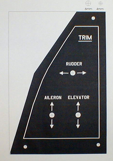
in my case) to create the paper backing sheet as in Figure 1. Note that
the centres for any holes are marked. This first sheet is a sacrificial
one used as a template for drilling the perspex.
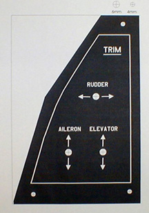
Fig 1. Paper Backing Sheet.
Click on any image for
a larger picture
2.
Having
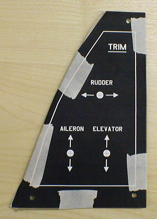
cut the perspex to the correct shape and size, attach the sacrificial sheet
to the front of the perspex panel using something like masking tape as
shown in Figure 2.

Fig 2. Ready for Drilling.
Click on any image for
a larger picture
3.
Using
the paper sheet as a guide, carefully drill the required holes through
the paper and perspex sandwich. To drill through perspex (and indeed most
plastics) I've found that wood drills (Brad Point) seem to work best but
remember to drill at a fairly slow speed with not too much pressure. If
you can - a drill press is an invaluable tool for this kind of work, smaller
bench top versions can be purchased in the UK for as little as 40 UKP and
are a very useful addition to any workshop.
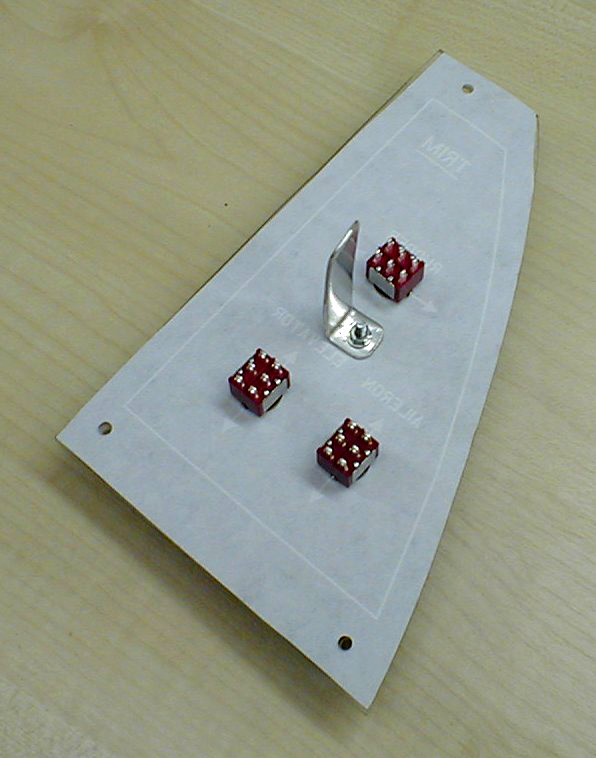
With the necessary holes drilled, its time to prepare our final backing
sheet. I found the best tool to cut out the holes is (not surprisingly)
a hole punch, again - these can be purchased for very little money and
are another valuble addition to the workshop. For slots or other irregular
shaped holes, avery sharp utility knife or a scalpel can be used - a
metal straight edge will help ensure accurate cuts.
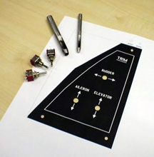
Fig 3. Hole Punches and Switches at the Ready.
Click on any image for a larger picture
4. With all the holes now drilled, the switchgear
can be mounted as shown in Figure 4. Note the addition of the aluminium
bracket which I'll use to anchor the wiring to. This will prevent wires
from being pulled off the switch connections should someone (me) inadvertently
yank the cable.
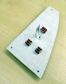
Fig 4. Switches and Cable Tie Mounted.
Click on any image for a larger picture
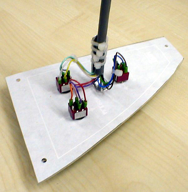
5. Now that the switches are all in place,
the wiring can be connected as shown below. Note the (excessive) zip-ties
anchoring the cable.
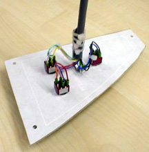
Fig 5. Wiring Complete.
Click on any image for a larger picture
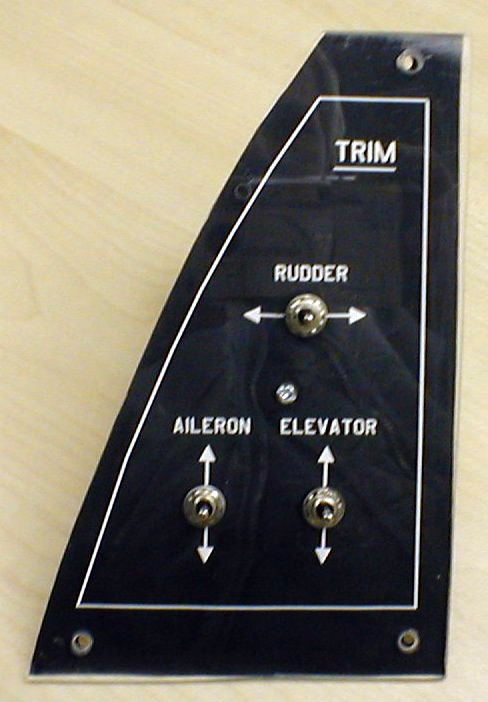
6. Now the panel is complete. Unfortunately,
reflections in the bright lights of the workshop don't show this panel
as it really is.

Fig 6. Finished Panel.
Click on any image for a larger picture
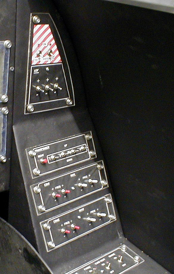
7. This panel can now join its comrades
and prepare for some serious abuse.
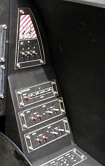
Fig 7. Right-Hand Cockpit Console.
Click on any image for a larger picture
Footnote:- The panel shown in these examples is indeed
wrong. The Ailerons should of course be trimmed left/right and not up/down
but hey, this was only a demo - sue me. For more info about this cockpit
and its assembly, please visit www.flightlab.liv.ac.uk/cockpit
or www.x-plane.info.
Copyright ©Roy Coates - Jan 2002
|