Archive for June, 2009

Building Recreational Flight Simulators is complete!

Friday, June 26th, 2009

Mike Powell’s new book, “Building Recreational Flight Simulators” has been sent off to the publisher!  This book is the much anticipated sequel to “Building Simulated Aircraft Instrumentation”.

Keep an eye on Mike’s Flight Deck website for price and availability.  The completed books are due to arrive some time in August.

Way to go Mike!

Simple 16 input board for EPIC

Tuesday, June 9th, 2009

In reworking the wiring for the F-15 simulator, I’ve decided to neaten it up with some custom circuit boards using the PCB Isolation Routing routine.

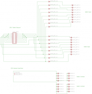
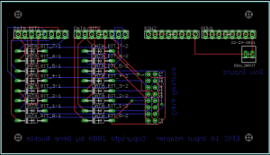
I’ve developed a simple 16 input board that connects to the EPIC primary interface board and uses screw terminals to make wiring easy.

I’ll be uploading the board files when I’ve tested them.  Until then, here’s what it looks like:

epic_16_input_schematicepic_16_input_board

I should have the first board made on Saturday.

[Updated 26Jun09]

A run-in with the H1N1 flu virus pretty much scrapped that weeks’ work.  I hope to get back to it tomorrow.

Making printed circuit boards without chemicals.

Sunday, June 7th, 2009

In doing research for making wiring boards for the EPIC (used in my F-15C project) I discovered a technique for making printed circuit boards (PCBs) that doesn’t involve any etching chemicals.

The process is called PCB Isolation Routing and is done by using a CNC router with a VERY small “V” bit in it.  The bit used has a tip diameter of about 0.007″.

The key to the whole process is being able to generate code to create the PCB.  This can be accomplished with the free version of Eagle PCB in combination with a free program called PCB-GCODE

PCB-GCODE is a plug-in for Eagle that will take your board layout and generate the needed code to drive any standard CNC router that understands G-code.

If you head over to this site, you can get a pretty good overview of the process itself.

In order to use this process with my ShopBot, I needed to come up with a way to hold down the PCB material while the machine was working on it.  Below is the jig I created.
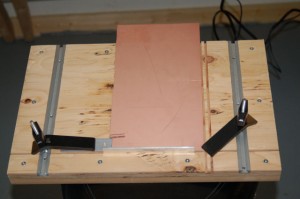
PCB hold down jig

PCB hold down jig

When you add two more hold downs, this jig can hold down a pretty good sized board.  The jig itself is 11-3/4″ high and about 13″ wide.

The grooves you can see cut in the right corner are for alignment blocks.  They consist of two 6″x3/4″ .125″ thick aluminum bars that are used to locate the PCB material in the lower right hand corner of the jig, where the X & Y “home” is.  By leaving the bars in place, you have a repeatable point for locating your material when you flip it if you’re doing double sided boards.

When my double sided PCB stock arrives next week, I’ll put together a video showing how it works using my new EPIC input boards as an example.
Simpits server replaced…

Saturday, June 6th, 2009

Today I was _finally_ able to replace the 7 year old server that simpits.org and it’s services ran on.

With the addition of WordPress, the poor machine just couldn’t keep up.  The original server was an early Athalon 1400+ with 512MB of RAM.  The new server is a Dual Core AMD system with 2GB of RAM and a 400GB SATA drive.  I really hope this improves the site response time for the main Simpits site as well as the other WordPress blogs hosted here.

I appreciate your patience during the time things were insanely slow around here. 🙂