8
 Using the 7 Segment display controller
Let's start with wiring your 7 Segment displays.
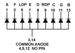
Use COMMON ANODE displays.
It is also highly recommended that you use current limiting
resistors, as you can seriously damage your whole EPIC circuitry when too
much current is drawn!
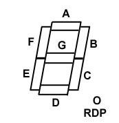
You should have a document from the supplier of your displays
that shows which pins controlls which segment. If you don't have this information
available, you need to find it out by yourself.
Here's an easy way:
Place a 1kOhm resistor in line with the + wire from your
power supply. Usually, the common pin is shorted to another pin. Find that
one before you continue. Once you found it, put the + wire (with the resistor)
to one of these two pins. Touch the other pins with the - wire from your
power supply and write down which segments lights up.
You should end up with something like this:
Ok, now we can start with soldering the wires
from the 20 ribbon wire. Solder the wires as follows:
|
Wire-#
|
Segment
|
Wire-#
|
Segment
|
|
1
|
A
|
2
|
B
|
|
3
|
C
|
4
|
D
|
|
5
|
E
|
6
|
F
|
|
7
|
G
|
8
|
H
|
|
9
|
Anode 0
|
10
|
Anode 1
|
|
11
|
Anode 2
|
12
|
Anode 3
|
|
13
|
Anode 4
|
14
|
Anode 5
|
|
15
|
Anode 6
|
16
|
Anode 7
|
|
17
|
Not used
|
18
|
Not used
|
|
19
|
+5V
|
20
|
Ground
|
Use wire 8 to control your "dot".
As you know, you can control up to 32 7-segment displays
with one controller. You can control up to 8 displays using one 20 ribbon
wire. To do this, you need to connect the same segments from the individual
displays. You end up having all the displays connected to the module thru
one display. Now solder the "Anode" wires to either the ground pin of each
display or the pin that is shorted with the ground.
That's it0 as far as wiring goes. Now for the coding.
Coding the 7-segment display controller is a bit different
compared to the 32 point output module. First of all, you don't need to
write a definemodule statement, but you need to define your displays. You
do this using the "Definedisplay" command. Let's define that display that
is soldered to "Anode 0".
#define Display1
0
Definedisplay(Display1,2,0,1,0,0,false,0b00000001)
Hmmmmm... Looks a bit complicated, doesn't it? We'll examine
this code now:
Display1
"Display1" will be replaced with "0" and simply means
that it is display no. 0. Remember, you soldered the "Anode 0" wire
to this display, didn't you?
2,0,1
"2" is the module-#. If you are not using Flightlink radios,
this number is always 2. "0,1" represent the physical starting digit
and the
number of digits. If you have, for example, soldered your
display to "Anode 3" and you have 4 displays connected, these numbers would
change to 3,4.
0,0,false
These are placeholders for the limits and the wrap flag
and are not used.
0b00000001
The bit 7 control bits are used to control special functions.
A "0" for example, will turn on the decimal point. Each bit is for a different
digit. The bit on the rightmost side controls digit 0, bit 2 controls digit
1 and so on. In the example above, the decimal "." is turned off for display
0 and turned on for all the other displays that might be connected.
Before we write a code that actually does something, we'll
take a look at the commands you can use to control your displays:
|
Command
|
Example
|
Explanation
|
|
Setdisplay
|
Setdisplay(0,8)
|
Sets display 0 to 8
|
|
Adddisplay
|
Adddisplay(0,1)
|
Adds 1 to display 0
|
|
Subdisplay
|
Subdisplay(2,4)
|
Subtracts 4 from display 2
|
|
Swapdisplay
|
Swapdisplay(0,3)
|
Swaps display 0 and 3
|
With all this, we're going to write a code that
counts from 0 to 9.
#define
Test 0
#define Fastscan
0
definemodule(0,Fastscan,0,7)
definedisplay(Test,2,0,1,0,0,false,0b00000001)
:Buttondown
{
Setdisplay(Test,1)
Delay(50)
Setdisplay(Test,2)
Delay(50)
Setdisplay(Test,3)
Delay(50)
Setdisplay(Test,4)
Delay(50)
Setdisplay(Test,5)
Delay(50)
Setdisplay(Test,6)
Delay(50)
Setdisplay(Test,7)
Delay(50)
Setdisplay(Test,8)
Delay(50)
Setdisplay(Test,9)
Delay(50)
Setdisplay(Test,0)
}
Definebutton(XX,on,Buttondown)
Quite confusing, isn't it? ;) Work a bit with it, and
it'll become much more clear.
|
Copyright 2000 Martin Ingold
|
