For a while now I’ve wanted to replace the crappy, noisy pots that I’d used in my Jentron MK2 gimbal that was in the 109F/X #0 cockpit. They were so bad that it was impossible to use the gimbal for flight at all.
The best way to replace a mechanical potentiometer is to use a hall effect device. This is essentially a sensor that will output a 0 to 5v signal based on the position of a magnet. I’m using the Allegro 1302 for this project. It works very, very well and can be a direct replacement for any three wire pot installation.
My design uses a 7/8″ (22mm actually) bearing with an 8mm center bore. The center bore allows you to use a “traditional” Bic pen body as an input shaft. You can press the body segment into the bearing and it won’t be coming out any time soon! You can purchase the bearings here: http://www.vxb.com/page/bearings/PROD/SB/Kit1063
I installed the pen body into the bearing and then glued a pair of 1/4″ square neodymium magnets (oriented NS-pen-NS) to either side of the pen body with some thick Cyanoacrylate glue. Works great!
In order to be a direct replacement for the pots, I needed to add similar control arms to them. I did this by laser cutting a press-fit back plate that I threaded for #4-40 screws.
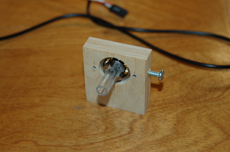
Here’s the end result so far:

I then bolted it all together and attached the control arms with screws:

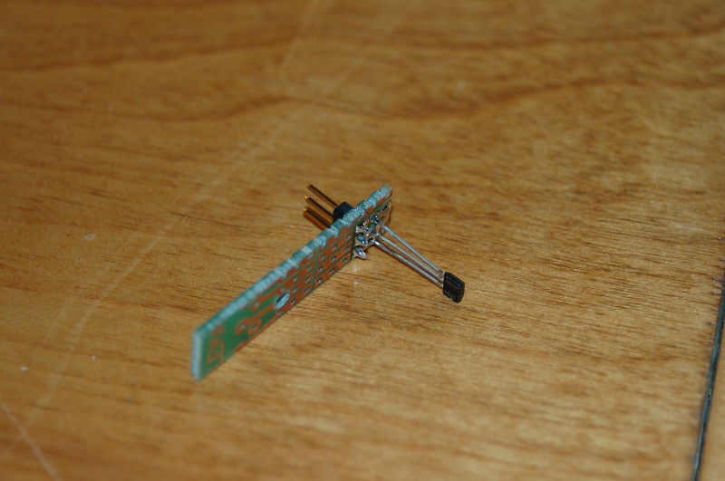
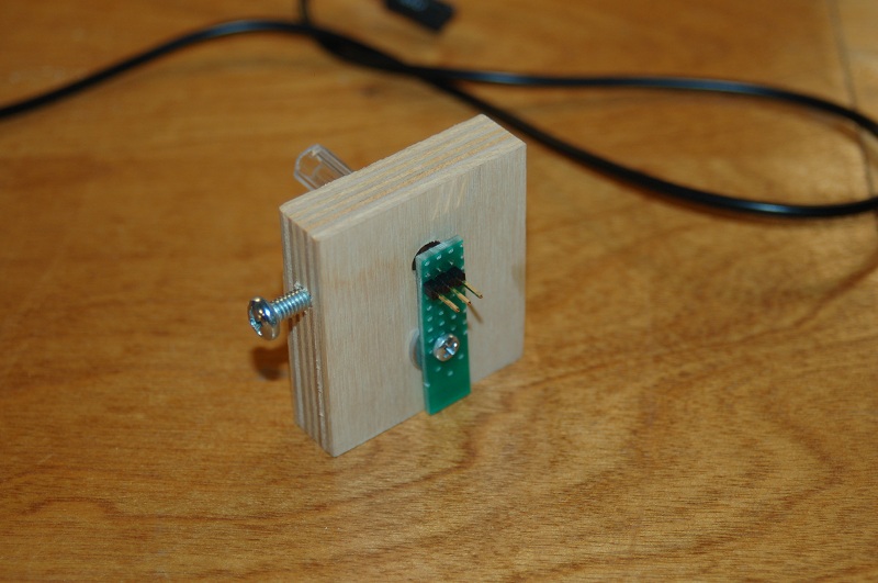
The tiny circuit board holds the A1302 hall effect sensor so that it’s in the exact center of the pen body and aligned with the two magnets.
After cutting out the old pots and adding a couple of terminal blocks, the new control inputs were installed:

When connected to the pots, the joystick calibration screen in Windows would show a constant jitter that ran +/- 200-400 around the center point. With the new A1302 based inputs installed the jitter was ZERO. I’m really looking forward to getting these installed into the rudder pedals, toe brakes and throttles!
Here’s a more detailed how-to on building these for yourself:
Here’s the parts you need:
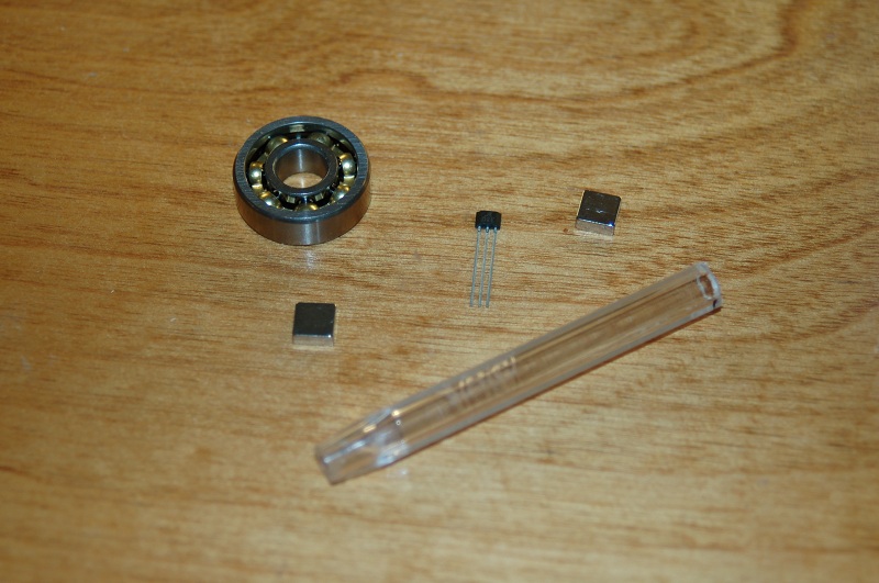
The parts shown are a 22MM bearing (just a little shy of 7/8″ diameter), two 1/4 x 1/4 neodymium magnets, an Allegro A1302 hall effect sensor and a Bic pen body.
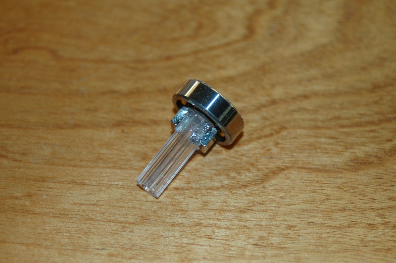
Using a vice, carefully press in a short segment of pen body into the bearing – do NOT hammer it! The pen body plastic is very brittle. Steady force using a vice will “drift” in the pen body quite easily.
Next, glue the two neodymium magnets to opposite sides of the pen body – the magnets should be oriented N-S (they’d come together if the pen wasn’t in the way). The way I did mine was to rest the magnet on the inner race of the bearing with a business card keeping it from physically touching the race. I then used “thick” CA (cyanoacrylate) to glue the magnets in place – have some kicker handy to speed up the cure process.
You should end up with something that looks like this:
Now you need to build the board that will hold the sensor in place. I used a small slice of copper clad perf-board. This holds the 3 pin connector and the A1302 very well.
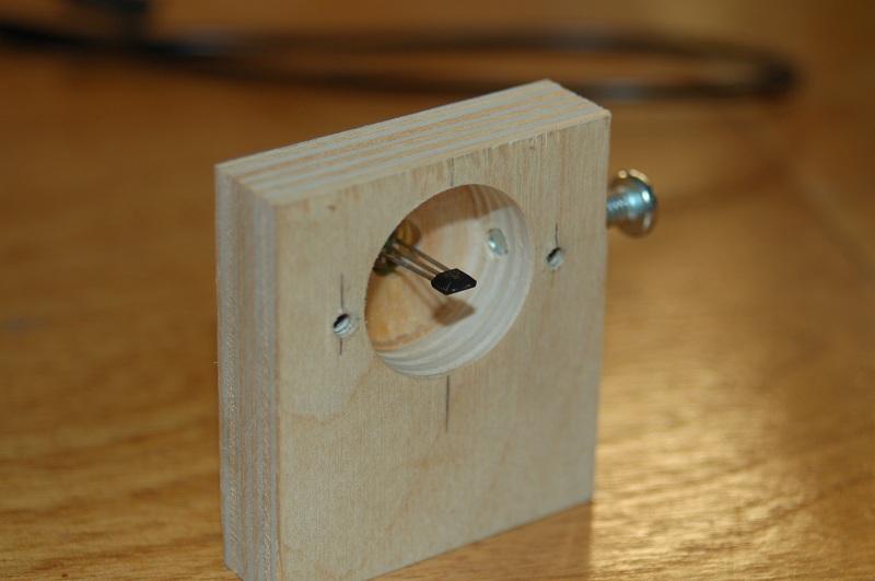
Next, you want to get some 1/2″ or 3/8″ plywood and bore a 7/8″ diameter hole in it using a forstner bit. Dont’ bore the hole completely through – leave about 1/8″ of material. Then drill a 1/4″ hole using the same center as the 7/8″ hole. I use a set-screw to hold the bearing in, but you could easily hot-glue it in if you’re careful to keep the glue out of the bearing races. Tape the bearing in for now so you can align the hall sensor properly. A properly aligned sensor will fit in the center of the pen body with the magnets on either side of it.
You should end up having something that looks like this:
Assembled, it should look like this:
You can connect any kind of pushrod arm, gear, or whatever to the pen body – just don’t apply too much side force to it. Too much side stress will crack the plastic. This setup gives 180 degrees of usable travel and works very well! The bearing size that you get should have an inner diameter just a tiny bit less than the widest point on the hexagonal Bic pen body. This allows for a very tight friction fit that doesn’t require any adhesive to hold it in place.
You can easily custom design your own bracket for this – this was a simple prototype that proved out the technique and a refined version will end up in my ‘109 as well as a replacement for the pitch axis sensor I screwed up in my BRFS gimbal build. ![]()
Hello Gene
I have been following your builds and projects with great admiration. I want to incorporate the hall sensor into my replica Fw 190 throtle. Could you explain to me “(oriented NS-pen-NS)” and what does it mean? Where can I get the circuit board that holds the hall effect sensor? And lastly I would be willing to pay for you to make 2 “press-fit back plate and 2 control arms. Great work and much success. Thank you.
Jose
“NS” means “north-south”. You want to orient the magnets so if the pen wasn’t in the way, they’d snap together.
The circuit board is a simple “perf” board that you can find at any local Radio Shack. It has little parallel strips of copper drilled on .100 centers and a tiny gap between each row. It may also be called “strip board” – see the illustration for “Tri pad” strip board here: http://en.wikipedia.org/wiki/Stripboard This is what I used.
Unfortunately due to a serious health issue, I won’t be working on much of anything until after the first of the year. If you can afford to wait that long, I’d be happy to help out. Otherwise you’d be better of trying to make those parts yourself, it’s not that hard. The arms can easily be made from 1/8″ aircraft ply – drill the center hole a bit undersized and file it to shape with a small hobby file.
g.
What are you using to interface these sensors to the computer?
For this particular project, I’m using a board called Plasma MM2, produced by Beta Innovations. You could use one of Leo Bodnar’s boards as well.
Gene,
I am working on a similar project – one to replace the awful pot in an X52’s throttle to a hall effect sensor.
I have everything in order, except for the strength of the magnets and the sensitivity of the required sensor. What strength magnets are you using for this project?
Also, what is the output voltage of the sensor based on the position of the magnets?
Thanks,
Shawn
Shawn, as I stated in the article, I’m using a 1/4″ square, .100″ thick neodymium magnet. The Magcraft part number for them is NSN0610/N40.
I don’t recall what the exact voltage range I was getting, but I’ve been told by another builder that he gets a greater range by using a single magnet instead of two opposed.
g.
Very nice. Threw together a _very_ rough POC. Tested on Arduino. Working beautifully. I’m now adding a second ‘gang’ where another hall effect sensor (in my case UGN3503U’s) is oriented perpendicularly with relation to the sensor below it, that way it should give me the full 360 degrees, by combining both sets of readings.
Should also allow me to do on the fly re-calibration/compensation in case my manufacturing processes are a little out of whack.
Hi
First, Congrat’s on a great project. I am building my own rudders, joystick and throttle/buttons and you helped me a lot by seing solutiong you adopted. I am also considering implementing Hall effect as a cheap, accurate and longlasting technology compared to pots. But I’m not shure about some things so if you can help me out :
– sensor reading…how wide is it ? Thing that bothers me is what kind of reading can I get in a narrow angle around central axis..normaly 0-25 degree on joystick axis. Theoretically I could get 12 bit resolution ( 4096 steps) from leo bodnars board, but it’s dependent on what sensor will read. So what has influence on this…one magnet and perpendicular sensor, two magnet setup like yours, bigger magnet, distance from sensor to magnet ??? Is there any rule of thumb to it ?
– I know magnetic orientation realy must be N-S. But the magnet orientation in relation to sensor should be irrelevant ? Becouse calibration is done in windows it shouldn’t matter what’s the magnet rotation. The reason I’m asking is becouse there are round magnets to by with central bushing for screw them to the axis which looks like more simple installation to me. There might be trouble becouse sensor has some Sinusoidal output – not linear like a pot, so we want to find magnet position where that sine output is most linear ?? Or is it exact sine wave across all magnetic field – so no matter how you rotate magnet ?
Thanks in forwards
Regards
You sir, just saved my budget! I was looking at a $40 per axle pricing for a factory-made angle sensor but I will definitely go this way!
Glad to hear it Rob!
At some point I’m going to do a redesign using diametrically magnetized neodymium magnets. It’ll allow the whole assembly to be smaller because you won’t need a magnet on either side of the sensor, just one up against the top of it. If you want to experiment, K&J Magnetics (http://www.kjmagnetics.com) sells them. The part # is D42DIA. They’re 1/4″ diameter x 1/8″ thick.
g.
Hi Everyone I really enjoy reading and following your projects I have one of my own but I haven’t found a circuit to help me I’ve been working on a Daftman 4 pot generator engine. It physically looks a lot like it. The problem I have is the wiring of the Hall effects for timing the firing of each pot so far I haven’t been successful in turning the whole shaft by the magnetic’s . My Magnetic are the neodymium magnets extremely strong and powerful. The rotors in the pots are constructed of 2′ round Aluminum rod the Neodymium Magnetic’s are 1″ Long x 1″ Wide by 1/2″ Thick. I used my lathe to plane the size of the magnetic’s into the Aluminum and it come out relatively okay. In putting them on the shaft which is a 1/2″ like the Daftmans except his was 3/8″ and his bearing were seal ball bearing type where mine are 1/2″ Pillow block bearings. The biggest problem I have is figuring out how to wire the Hall effect timing system into my system. Any and all help appreciated I’s pretty much a beginner and need as much help as I can get.
Thanks for listening to me ramble on. I have pictures but I don’t know how to post them on this.
DonaldL02
Donaldl@bluemarble.net
Hi everyone
1. I’d like to make a thottle similar to yours to use with my X-Plane 11 and I’d like to know what should be the angular range of the handle to get 0 to 5 volts (idle to 100%).
2. Is it necessary any electronic circuit to get a better performance?
Best regards
You don’t need an absolute 0..5v swing in order to build the throttle. The resolution of the ADC is more important – it gives you more “steps” between the min/max voltage that the sensor outputs. When you calibrate the throttle in X-Plane, it will use the min and max values coming from the ADC as the end points of the throttle travel in the simulator.
Thank you for your quick answer.