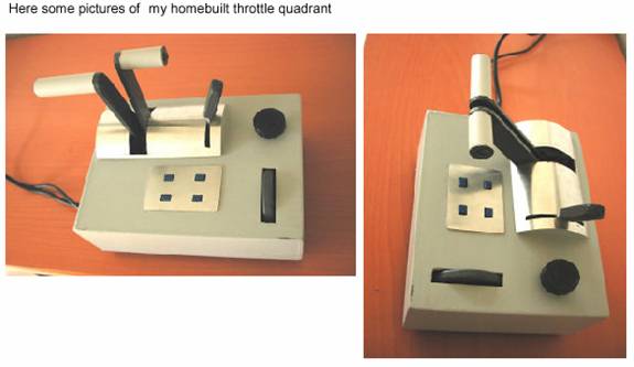
 In this description you'll find all necessary information of how
to build your own cheap but well working
throttle quadrant for PC-flight simming. But before starting
think about two things: In this description you'll find all necessary information of how
to build your own cheap but well working
throttle quadrant for PC-flight simming. But before starting
think about two things:
1. Do you have a little experience in handicraft things like,
sawing, drilling, soldering, painting and so on and do you have the tools for this? If so you CAN do it.
2. Can you get the necessary things like the trim pots, the ply
wood, the cables and the plug? If so you SHOULD do it.
How to start?
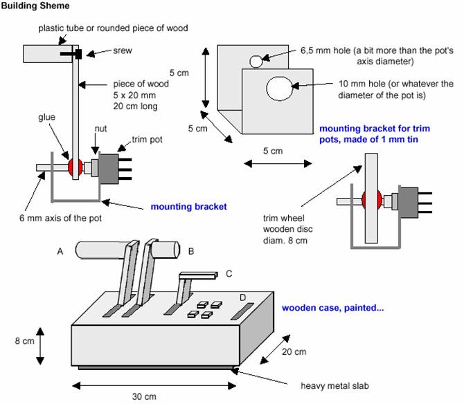
Start with building one of the mounting brackets
with a trim pot and a handgrip. If you succeed, build the other two or three (one could be a trim wheel).
Fix these brackets on a appropriate piece of
wood like 20 x 30 cm (8 x 12 inches) about 2 cm thick.
After having done this, its time for the first
electrical wiring to try out if it works.
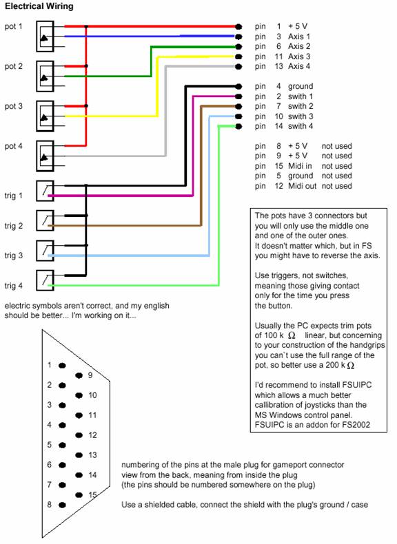
Take the 15 pin male plug and sold the several cables to it. Make a notice
which cable (coded by colours) is connected to which pin.
Now solder the other ends of the cables to the
pots and/or switches. To make it easier you can start with only one pot and / or one trigger.
BE SURE TO USE THE
RIGHT PINS, a mistake might cause some damage in in your PC (even I don't think so).
If you have finished this, it's time to connect
your throttle quadrant to the PC. As I mentioned you can connect it directly to the
game port. Now go in Windows to
Start - Settings - Game controllers.
Add a new one like two axis - two switches or
whatever you want. At this time its only about to try out if it
works.
When added this new device you should get a connect: OK. If so, the worst thing is done. If not there is
something wrong, probably concerning the connected pins or the pot itself. DISCONNECT IT
IMMEDIATELY!
If you got the OK you should be able to check
it's properties. So now move the handgrip and you should see a move of the position indicator on the screen.
Push one of the triggers, one of their indicators should flash. It still needs to be calibrated but not at this
time.
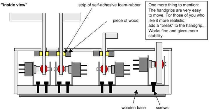
So now continue with the rest of the handgrips
and switches (try to get some which can be mounted in the top of the box by a nut - that's the easiest way,
you only need to drill a appropriate holes into the top piece of wood).
The last thing to do is to build the box with
the holes in the top around the wooden base. Use some sandpaper and finish with some paint. I would
recommend to build the box that way that it's top can be removed for maintenance. For more stability you fix a metal
slab underneath the wooden base.
Now you're done and you connect it again, add it
as an 4 axis 4 switch device, give it any name and calibrate it. In FS2002 you now have two
controllers which you can assign the different axis.
I hope my description is good
enough to make you understand what's it about. I also hope you dare to start -
it's not as difficult as it sounds...
My
assignments of the 4 axis:
|
A |
B |
C |
D |
The 4 triggers are assigned to flaps up / down, gear and parking break |
|
single prop
|
throttle |
- - |
prop |
elev. trim |
|
twin prop
|
throttle 1 |
throttle 2 |
prop both |
elev. trim |
|
twin jet |
throttle 1 |
throttle 2 |
spoiler |
elev. trim |
If you connect this throttle quadrant directly
to the gameport, it will work fine. If you decide to connect it via USB (using an
game port to USB converter) you will notice, that the elevator trim isn't working
sensitive enough. This is because the USB input allows only 16 or somewhat values for an
axis. This is not enough for rudder trim
There are several solutions: Change the elevator
trim effectiveness in the relevant aircraft.cfg, try some tweaking in the sensitivity settings of
the axis in FS 2002 or do what I did:
I wired the elevator trim axis of the throttle
quadrant as the 4th axis of my joystick, which is connected to the game port. So I could add a 5th
axis to the throttle quadrant which is wired as it's 4th axis. I assigned it to Mix (I built it
as a turn knob, which you can see in the pictures. This is the reason why there are two cables coming
out of the box...)
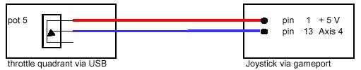
The regular trim pot of the joystick's 4th axis
has to be disconnected.
|
And these are the prices for the material I
used: |
|
1 15 pin plug |
1.5 Euro |
|
2 m of 10 wire shielded cable |
2.5 Euro |
|
3 trim pots 200 K linear (for the hangrips) |
3.9 Euro |
|
2 trim pots 100 K linear |
2.6 Euro |
|
4 switches |
6.0 Euro |
|
some wood |
4.0 Euro |
|
some tin |
4.0 Euro |
|
some screws, nuts etc... |
2.0 Euro |
|
some paint, glue cable... |
3.0 Euro |
|
Total
|
30.00 Euro
= ~ $30 US |
It took me about 2 days to build it, but the
real net building time lasted only a few hours. And believe me, building was at least half the fun...
|
