Cockpit Interface Electronics:
Part One: EPIC
Ever since the first home computer ran a flight simulation, there have been people that wanted to build a cockpit of their very own. Unfortunately, until recently this has been too expensive or technical an undertaking for many people. The last few years have seen some amazing products come to market. From high-end interfacing systems like EPIC to the multi-purpose boxes made by GoFlight!.
What I'm going to do here is review the three products that I've got personal experience with. There are other solutions available I'm sure, but these are the ones I spent my money on. Hopefully this review will not only allow you to make an informed purchase, but encourage those of you on the "fence" about whether or not to enter this most fascinating hobby.
First on the list is EPIC. EPIC is an acronym for "Extended/Programmable Input Controller". This device was originally developed as a 16 bit ISA card for the IBM PC and compatibles by Ralph Robinson of R&R Electronics. It featured 16 analog channels and 304 digital or "switch" inputs as well as an expansion bus that supported such things as 32 "point" output boards that could be used to control indicator lamps. Other options included a 7 segment display controller that would drive up to 32 digits per board and a board that would handle rotary encoders for handling things like radio stacks. A number of successful products were EPIC based, including the KR1 Avionics Stack by Flight Link. The most important feature of the EPIC board is that it can work with just about any piece of software. Both the old-style ISA board and the new USB based EPIC can send keystrokes to the host computer based upon programmed input events.
The EPIC has one feature that makes it stand out from all the other products out there. It has its own programming language called EPL. EPL code is compiled on your PC and uploaded to the EPIC board via a special program. Below is an example of EPL that I copied from an example that is supplied with the USB EPIC:
//---------------------------------------------------------------------------
#include <EPICDEFS.hpl> //in EPIC\Include directory
//define input modules to scan. There can only be a maximum of 16 FASTSCAN rows
in the system.
// These should be used for Rotaries, view hats, triggers, etc.
definemodule(0,FASTSCAN,0,7) // Scan DB15 connectors on first expansion module
definemodule(1,SLOWSCAN,0,16) // Scan all of Module 1 on first expansion ribbon
definemodule(2,SLOWSCAN,0,16) // Scan all of Module 2 on first expansion ribbon
#include "ScanAllDevices.hpl" // In local directory
//---------------------------------------------------------------------------
:INIT
{
}
The sample is written to "enable" the switches attached to the DB15 connectors on the Expansion Module as well as the first two "Modules".
If you click here you can see a picture of my Expansion Module. The image isn't that great but you get an idea of what the board looks like. On the right edge of the board are two connectors. The uppermost one provides access to the 16 analog inputs. These analog inputs are also present on the DB15 connectors which allows you to hook a standard analog joystick up to the EPIC board. One thing I should note here, the EPIC board (when loaded with an appropriate EPL program) will look like a bunch (or one!) joystick to Windows. The ISA version of EPIC works this way by default with no need of an EPL program.
The lower connector is where the 8x32 input matrix is accessed. This image shows you how that works. This is the current configuration of the EPIC in my F-15C Eagle project. The two rows of terminal strips are the Module rows and the single 8 position terminal block is the Data row. The center of the picture shows the terminal strip for the 16 analog inputs. The Expansion Module also provides a +5VDC and Ground connection on the Analog connector. This is because EPIC requires the use of 3 wire potentiometers when not using the DB15 connectors for joystick axis interfacing.
If you're still looking at my EPIC configuration, you'll notice there is a ribbon cable leading to a board mounted above the Expansion Module. This is the 32 Point Output Module. It can drive up to 32 on/off type devices such as lamps or stepper motors. It requires a separate 12VDC power supply to power the electronics on the board. The board is also designed to take an external power supply for the use of devices that the board is activating. For instance, if you're using the board to turn on 24V lamps, you would connect a 24VDC power supply to the board's auxiliary power input connector.
The last connector of interest on this board is the big 37 pin connector that is positioned to the right of the 3 DB15 connectors. This is how the Expansion Module connects to the EPIC. It should be noted that a special Expansion Module and "Y" cable can be ordered to increase the input capability of the EPIC. The option will allow the EPIC to access both Expansion Modules giving you 608 inputs. It does not (as far as I know) allow access to an additional 16 analogs or the extended EPIC Bus on the second Expansion Module.
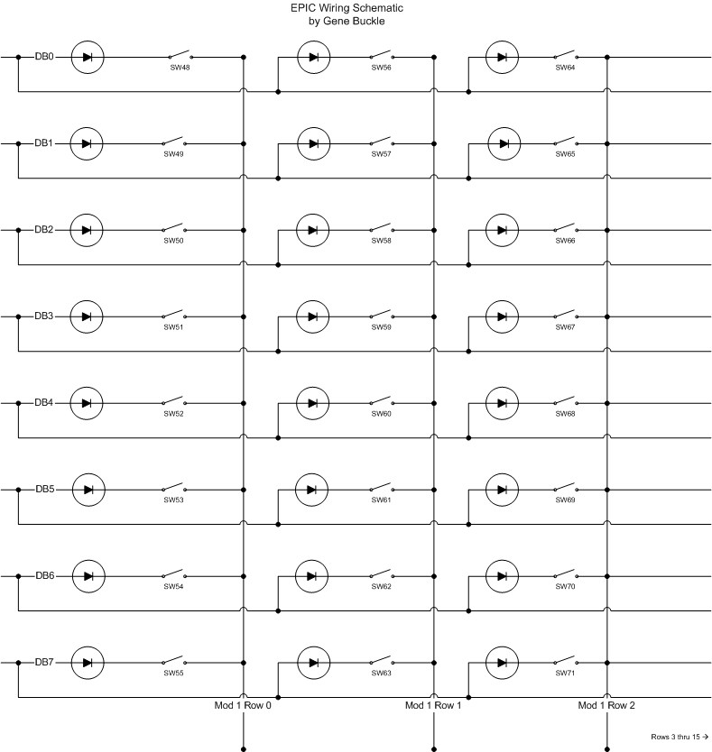
The EPIC uses an input method that is very similar to how your keyboard is scanned. EPIC uses an 8x32 matrix for the main input Modules. This gives up to 255 switch inputs. Each input is diode isolated so an individual switch state can be correctly detected. You can view a schematic here that illustrates how the input matrix is wired. Along the left of the schematic are the 8 "data bit" rows and along the bottom are the 32 "module" rows. Modules 1 and 2 each contain 16 rows and is accessed via the 40 pin header on the Expansion Module. Module 0 is accessed via the DB15 connectors on the Expansion Module. Module 0 supplies 48 switches, giving the EPIC-wide total of 304 inputs.
Without the diodes isolating each point of the matrix, EPIC wouldn't be able to discover more than a few switch states. As an example, press as many keys on your keyboard as you can at once. Since your keyboard is not using a diode-isolated scan matrix, it can only "see" a few of those many keys that you pressed.
When you close a switch in the EPIC input matrix, you're causing an input event to occur. If the EPIC is running EPL that tells EPIC to "be a joystick", that input event will emulate a joystick button press to the host computer. When in "full on" joystick mode, the EPIC will appear to the Windows host as 8 joysticks with 32 buttons each. Impressive, eh? The most common use of the EPIC is not in the "joystick" mode however. Most users will tie a bit of EPL code to a specific input event. For instance, you could write an EPL routine that would send a "G" to the computer when the landing gear lever was moved. That same bit of EPL code could also turn on or off the landing gear position lamp, depending on the state of the gear. Here is a small example of this:
#define FASTSCAN 0You can also talk directly to the EPIC using a small SDK that is available. It allows you to send data to EPIC via a "pigeon hole". When data is inserted into one of these "pigeon holes", EPL code running on EPIC can read it for doing things like setting specific numbers on the 7 segment display.
When there is no software loaded aboard EPIC, it appears as a generic USB HID to the host. Only when an EPL program is loaded will it appear to the host as anything else.
The EPIC Bus can handle any combination of modules, up to 16. There are four basic modules that are currently available:
32 Point Output Module
32 Digit 7 Segment Display Controller
Gauge Module - Supports up to 8 air-core or milliamp-meter style indicators
Rotary Module - Supports up to 16 mechanical and 4 optical rotary switches
EPIC is a popular choice among what I call the "first generation" of cockpit builders. EPIC was first on the block and has accumulated a very dedicated following. Nearly every project I've seen that involves a real aircraft cockpit as the base is usually EPIC driven.
Technical support from R&R Electronics is top notch. Ralph is always friendly and helpful when you've got a question or a problem about EPIC. He's been known to fly across the country to help people out with tricky EPIC problems. Any bugs found in the tools that come with EPIC are usually fixed quickly once brought to his attention. The EPIC user community is also a helpful bunch and they're willing to go the extra mile to help out a new user.
Is EPIC for everyone? No. EPIC is a very flexible and powerful device and as such can be complex to use to its full potential. That's not to say that it's too complex for the average user to understand, but it does take some dedication to learn the product.
One of the things that will make people shy away from EPIC is the price. The base USB EPIC is $359 and requires the Expansion Module ($95), which gives you a basic entry cost of $454. For the cockpit builder on a budget, this is a very expensive solution. When you begin adding other modules such as the 32 Point Output module ($105), it can get very expensive quickly. EPIC is the most powerful of the available cockpit interfacing solutions, but it's also the most expensive.
For sales information you can head over to the Flight Link website. They are the US distributor for EPIC and it's accessories. The site address is http://www.flightlink.com/epic.
For technical information on EPIC and for links to projects that use it, head over to Ralph's original R&R Electronics site located at http://www.mindspring.com/~rrelect.
If you have any questions or comments, please feel free to contact me at geneb@deltasoft.com. This review will be updated as questions are asked so keep checking back for new data periodically.
Gene Buckle, February 8th, 2004
Last Updated: 08Feb04